GR-1 ZONE

GR-1 ZONE
This page contains GR-1 information about;

GR-1 ZONE FAQ - Manuals - Factory Presets - MIDI Troubleshooting
GR-1 ZONE SPECS - Dimensions - RAM - GK Pickups - Power - Battery
GR-1 ZONE ACCESSORIES - Expansion Kit - RAM Cards - Pedals
GR-1 ZONE ROM IC VERSIONS - ROM Revisions - Bug Fixes
GR-1 ZONE ERROR MESSAGES - Common Error Messages And Troubleshooting
GR-1 ZONE BATTERY REPLACEMENT - Internal Battery DIY
GR-1 ZONE TACT SWITCH REPLACEMENTS - Part Numbers And Instructions
GR-1 ZONEE CUSTOM MULTI-BANK RAM CARDS - An Innovative RAM Card Design From Deutschland
SUPER JX ZONE FAVORITE DIY TOOLS AND DIY VENDORS - Tips For DIY Freaks Who Like To Save $$$
GR-1 ZONE INITIALIZE THE GR-1 TO A STATE OF "FACTORY FRESH" - These Procedures Will Erase Everything
GR-1 ZONE RESTORING THE ORIGINAL FACTORY PRESET PATCHES - Load The Original 64 Patches From ROM


GR-1 ZONE     GR-1 ZONE GR-1 ZONE - BATTERY GR-1 ZONE     GR-1 ZONE
ANIMATED_STAR I think these two topics are important enough to place at the top of all my synth INFO webpages

1) I buy a lot of broken synths on eBay and I'm able to fix about 90% of everything I find. It's usually a simple fix. If you have a synth with no power or intermittent problems after it warms up, it's probably due to the fact that back in the 1980's Roland and other synth makers used sub‑par solder and/or not enough solder to hold components in place. After 30+ years, the solder begins to break down and hairline fractures appear. This occurs at a higher rate for components which generate a lot of heat like Bridge Rectifiers, Power Transistors, large Electrolytic Capacitors, power input jacks and audio jacks which get a lot of use. The best approach is to use a magnifying glass and carefully inspect the backside of the circuit board. If you spot any suspect areas, re‑flow a hefty amount of NEW solder

FRACTURS_AND_MIDI

2) I receive a lot of eMails and field many questions at synth related forums and also on Facebook. The most common question I get about problems with a synth has to do with errors when trying to load Patches and Tones. About 99.9% of the time, the problem always turns out to be a crappy MIDI interface. If you have a cheapo MIDI interface which looks similar to the one shown on the right... throw this piece of shit in the trash! Do It Now. Seriously! This thing is total junk and you get what you pay for. Inexpensive MIDI interfaces like this are unable to properly regulate the buffering of MIDI data. They will work fine with simple messages such as CC, Note On, Note Off, etc... however, when you try to send SysEx messages which are much longer, the SysEx data cuts off after only sending a few bytes. Investing in a higher quality MIDI interface will solve Load/Save errors and other communication problems

      These MIDI interfaces have been tested and will work with large SysEx Dumps:
        Focusrite Scarlett 2i4 2nd Gen    M-Audio Profire 2626         ESI Midimate eX          ESI Midimate II
        Focusrite Scarlett 4i4 2nd Gen    Miditech MIDIface II Thru    Yamaha UX 16 USB/MIDI    MOTU 823 mk3
        Focusrite Scarlett 6i6 3rd Gen    Tie Studio MIDI 1i1o         Miditech MIDIface 4x4    RME FireFace UC 2X2
        iConnectivity mio 1x1             iConnectivity mioXC 1x1

      These MIDI interfaces are shit and do not work with large SysEx Dumps (some might w/special driver):
       AVID/M-Audio Fast Track Pro       M-Audio MIDISport UNO         M-Audio MIDISport 1x1   M-Audio Uno
       M-Audio MIDISport 2X2             Lekato MIDI USB               Hosa USM-422 MIDI       Fore MIDI Interface
       DigitalLife MIDI-C01              Hosongnic, HiFangeow, etc...


* * * FAQ: GR-1 * * *
"You can use your favorite guitar as a controller; perform bends, trills, and hammer-ons without fear; edit patches in real-time, with actual knobs; and change programs (and some parameters) stomp box-style. It's the first guitar synthesizer I'd consider making friends with.... the GR‑1 is truly an instrument that respects the heritage of the guitar. That's important. Roland's sensitivity to guitarists may do more to advance guitar synthesis than any impending technological breakthroughs."
-- Electronic Musician Magazine, 1993 ---
    QUESTION     ANSWER720_SPACER
Where Can I Find Manuals For The GR‑1?         GR-1 MANUALS GR-1 Owner's Manual (v.92-6)      GR-1 MANUALS GR-1 Service Manual (v.92-11)

        GR-1 MANUALS GK-2 Pickup (v.89-7)                      GR-1 MANUALS GK-2A Pickup (v.00-01)                 GR-1 MANUALS GK-2B Pickup (v.02-1)

        GR-1 MANUALS GK-3 Pickup (v.03-1)                      GR-1 MANUALS GK-3B Pickup (v.04-5)                   GR-1 MANUALS GK-KIT-GT3 (v.03-1)

        GR-1 MANUALS GK-2A-KIT (v.97-7)                         GR-1 MANUALS GK-KIT-G (v.00-1)                           GR-1 MANUALS GK-KIT-GB (v.02-1)

        GR-1 MANUALS SR-GR1-01 Expansion Card (v.93-2)                         GR-1 MANUALS GR1-01 Service Manual (Color Inserts)

        GR-1 MANUALS Manuel du Propriétaire GR-1 (Français) (v.92-03)   GR-1 MANUALS GR-1 取扱説明書 (v.97-1)


Owner's Manuals for almost every synthesizer and effects device can be found at
        GR-1 MANUALS midimanuals.com


Super high quality PDF Service Notes and Repair Manuals for hundreds of synths can be found at
        GR-1 MANUALS synfo.nl
What Does The GR‑1 Sound Like?         GR-1 Demo Song GR-1 Demo Song (Using The SR-GR-1 Expansion Board)
How Do I Load An Alternate Set Of Patches? To load an alternate set of Patches a Mac, PC or LINUX computer with generic SysEx loader program is required

Note: If you want to automatically load the Factory Preset Patches, click here for info to initialize the GR‑1

[ WARNING!!! Everything in the internal memory will be erased! ]

To perform a Bulk Load


     Connect MIDI In and MIDI Out cables to+from your computer and the GR-1
     Run a generic SysEx loader program on the Mac, Windows or Linux computer*
     Open the *.SYX file
     Press the [ EDIT/SYSTEM ] button on the GR-1 (10 S-COMMON appears in GR-1 display)
     Press the [ PARAMETER/NEXT ] button three times (13 BLK DUMP appears in GR-1 display)
     Press the [ ENTER/YES ] button (13 SONG appears in GR-1 display)
     Press the [ PARAMETER/NEXT ] button three times (13 RECV appears in GR-1 display)
     Use generic SysEx program on Mac or Windows to SEND the file to the GR-1
     The GR-1 display window starts counting up from 111 to 284 and loads 64 Patches**
     After all Patches are loaded, the The GR-1 will briefly display "COMPLETE"
     Press the [ EXIT/NO ] button two times to return to normal play mode

     If the Bulk Load procedure did not work, verify SysEx Device ID = 17

* If the error message "MIDI OVR" is shown, refer to the section What Is A "MIDI OVR" Error Message?

** The count-up sequence looks a little odd on the display screen during the Bulk Load process. The sequence counts from 111 to 114 then 121 to 124 up to 184 then skips and restarts at 211 to 214 then 221 to 224 up to 284. i.e. 111,112,113,114,121,122,123,124... to 184 then 211, 212, 213, 214, 221, 222, 223, 224... to 284. This unusual counting sequence actually matches up with the Number Pedals (16 groups x 4 Patches in each group = 64 Patches total)

Alternatively, you can load all 64 factory preset Patches previously saved onto a RAM Data Card. See the section Memory Cards
How Do I Save All Of The Internal Patches To An External Device? To save all 64 Patches, you will need a Mac, PC or LINUX computer with a generic SysEx saver program

To Perform A Bulk Dump

     Connect MIDI In and MIDI Out cables to+from your computer and the GR-1
     Press the [ EDIT/SYSTEM ] button on the GR-1 (10 S-COMMON appears in GR-1 display)
     Press the [ PARAMETER/NEXT ] button three times (13 BLK DUMP appears in GR-1 display)
     Press the [ ENTER/YES ] button (13 SONG appears in GR-1 display)
     Press the [ PARAMETER/NEXT ] button one time (13 PATCHALL appears in GR-1 display)
     Use generic SysEx program on Mac, Windows or Linux to initiate SysEx data capture from the GR-1
     Press the[ ENTER/YES ] button two times (13 SENDING appears in GR-1 display)
     After all Patches are sent, the GR-1 will briefly display "COMPLETE"
     Press the [ EXIT/NO ] button two times to return to normal play mode
     Use generic SysEx program on Mac, Windows or Linux to save the captured data as a *.SYX file

     If the Bulk Load procedure did not work, verify SysEx Device ID = 17

* If the error message "MIDI OVR" is shown, refer to the section What Is A "MIDI OVR" Error Message?

Alternatively, you can save all 64 Patches onto a RAM Data Card... if you have one. See the section Memory Cards
I Can't Get The GR‑1 To Communicate With My Computer When Using A Librarian, SysEx Program Or Sequencer. What Should I Check? 1) Is the GR-1 set to SysEx Device ID = 17?
     Press the [ EDIT/SYSTEM ] button on the GR-1 (10 S-COMMON appears in GR-1 display)
     Press the [ PARAMETER/NEXT ] button three times (13 BLK DUMP appears in GR-1 display)
     Press the [ ENTER/YES ] button (13 SONG appears in GR-1 display)
     Press the [ PARAMETER/PREVIOUS ] button two times (13 DEVICEnn appears in GR-1 display)
     Press the [ VALUE/INC ] and [ VALUE/DEC ] buttons to change the display to read 13 DEVICE17
     Press the [ EXIT/NO ] button two times to return to normal play mode

2) Is the computer Sound Card, MIDI Controller, SysEx Librarian, etc... set to MIDI Channel 1?

3) Is the computer Sound Card, MIDI Controller, SysEx Librarian, sending MIDI data to the GR-1?

4) Make sure the patch librarian or SysEx program can send and receive SysEx data to and from the GR-1

5) Do you have two MIDI cables connected? Two are required. SysEx uses both MIDI IN and MIDI OUT

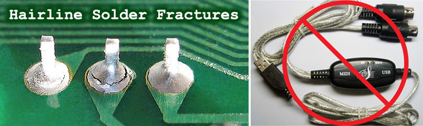
6) Is the MIDI interface on a USB hub? USB hubs are notorious for glitches. Plug straight into the computer

* If the error message "MIDI OVR" is shown, refer to the section What Is A "MIDI OVR" Error Message?
Can I Use My Guitar To Play Other Keyboards And Modules Like The MKS‑70, DX‑7, S‑550, FB‑01, M1, U‑220, Alpha Juno‑2, Proteus, JX‑8P, Moog Minitaur, Doepfer, PGH Modular, etc...? Absolutely... the GR-1 makes it possible to use your guitar to control just about ANY instrument with a MIDI IN port. Notes from your guitar and the GR-1 are converted into MIDI messages which can be used to drive an external MIDI sound module or keyboard. This is a very cool feature of the GR-1 which makes it a powerful piece of music gear for the studio or when playing live. Depending on the external MIDI device you are connecting to, there are three ways to control it;

        1) Multi-Timbral Six: Six or more parts transmitting in Mono Mode
        2) Multi-Timbral Five: Five or less parts transmitting in Poly Mode
        3) Simultaneous Six: Six channel Mono Mode

The GR-1 Owner's Manual goes into great detail about how to setup your external MIDI device and the GR-1. See the instructions which start on Page 6-2, "Playing An External Sound Module With A Guitar"
How Do I Change The Internal Back‑Up Battery?
CR2450 Battery
I recommend that you take your keyboard to a Roland Authorized Service Center. But...... if you're a real sicko like me and insist on saving pennies because you have that foolish "I can do that myself" attitude...... then...... detailed instructions are available. A big advantage of taking it to a Roland Authorized Service Center is that if they accidentally "pop" an IC because of static discharge, the cost is on them. On a difficulty level from 1 to 10, I rate this a 2... quite simple... No soldering required, as with some older synths. Just remove a bunch of screws and pop the cover

         MKS-50 GR-1 Battery Replacement Guide
How Do I Use The GR‑1 With An External Sequencer Using MIDI? Roland released a detailed guide for the GR-1 called "MIDI Sequencing with the GR‑1: Supplemental Notes". This is a useful guide covering a lot of information including MIDI Cable Routing, Initializing, Programming MIDI OUT Parameters, Setting The Multitimbral Parts, Recording The Multitimbral Parts, Recording the GR‑1's Performance Patch and Common Questions

         GR-1 "MIDI Sequencing with the GR-1" Guide
Why Does My GR‑1 Feel Unresponsive When Playing The Guitar? Some possible problems preventing quick response times while playing could be   
  • Pickup Sensitivity Setting (For proper adjustment, see page 1-6 of the GR-1 Owner's Manual)     
  • Chromatic Setting (For proper adjustment, see page 4-19 of the GR-1 Owner's Manual)     
  • Dynamics Setting (For proper adjustment, see page 4-19 of the GR-1 Owner's Manual)     
  • GK Pickup Not Positioned Properly (Refer to the GK Pickup Owner's Manual)
Why Does My GR‑1 Act Sluggish When Using It As An External MIDI Sound Module? The cable that connects from the GK Pickup to the GR-1 has 13 pins, so the internal sound source of the GR‑1 tracks very quickly. A MIDI cable only has two pins connected, so many messages must wait in line and therefore will take longer to get down the MIDI cord. Setting the parameter BEND = 0 will cut down on the amount of MIDI messages the GR‑1 will have to transmit and therefore possibly the waiting time

To set BEND = 0

     Press the [ EDIT/SYSTEM ] button and the "0" will start blinking
     Press the [ PARAMETER/NEXT ] button two times and the "2" will start blinking
     Press the [ ENTER/YES ] button
     Press the [ PARAMETER/NEXT ] button
     Press the [ VALUE/INC ] and [ VALUE/DEC ] buttons and set BEND to "0"
     Press the [ EXIT/NO ] button two times to return to normal play mode
What Is A "MIDI OVR" Error Message? The GR‑1 was designed back in Medieval times when the processor speed of a home computer was 20MHz... much slower than the models of today at 2GHz+. If the error message "MIDI OVR" is shown, the MIDI Send and Receive settings on your computer might be too fast for the GR-1 MIDI buffer to handle. Try setting the MIDI buffer size in your computer's SysEx program to a smaller value. For vintage synth gear like the GR-1, recommended values for Snoize, Bome and MIDI‑OX are 390ms
What Type Of Built‑In Effects Does The GR‑1 Have?
Reverb/Delay Type              Chorus Type 
  Room 1                         Chorus 1
  Room 2                         Chorus 2
  Room 3                         Chorus 3
  Hall 1                         Chorus 4
  Hall 2                         Feedback Chorus
  Plate                          Flanger
  Delay                          Short Delay 1
  Panning Delay                  Short Delay 2
    
Settings                       Settings
  Delay Feedback                 Feedback
  Reverb Time                    Chorus To Reverb Send Level
  Reverb Level                   Chorus Level
                                 Chorus Depth
                                 Chorus Rate
How Do I Initialize The GR‑1 To A State Of "Factory Fresh"? !!! WARNING !!!
Everything In The Internal Memory Will Be Erased. Everything... As In EVERYTHING!
Back-up Your Patches Before Initializing Your Synth.


HAZARD ICON

GR-1 Factory Reset (see WARNING!!!)
     ALL - Hold [ WRITE/COPY ], turn on the power and press [ ENTER/YES ]
     DEMO - Hold [ RECORDER ] then turn on the power
     PATCHES - Hold [ PATCH ] then turn on the power
     SYSTEM - Hold [ SYSTEM ] then turn on the power
     PROGRAMS 1 - 128 - Hold [ ENTER ] then turn on the power
     INIT SONG - Hold [ EXIT ] then turn on the power

Note: When initializing using ALL or PATCHES from the list above, the original 64 Patches + 200 PCM Tones are copied from ROM IC20 into RAM. Unlike most Roland synths from this era, there is no need to restore the Factory Patches from a SysEx file or a Data RAM Card after initializing or replacing the battery
The Fluorescent Indicator Panel (FIP) On My GR‑1 Just Bit The Dust. What Now?
SUMIDA COIL
If you find that the display on your GR‑1 has stopped working, there's a good reason for that. There is a driver coil on the Panel Board Assembly for the FIP. This particular coil is a known common point of failure with the GR‑1 and has been a nightmare for owners of the JX‑10, JX-8P, GM-70, DDR‑30, S‑50 and S‑550 synths/samplers as well. There seems to be no rhyme or reason as to when or if a coil will fail. The cause is a manufacturing defect which has been traced to the Sumida Corporation, the only supplier of this coil. Unfortunately, sources for replacement coils are very difficult to find. A supplier on eBay has some redesigned replacements which sell for $75 USD. Another hope is to find an old coil from a cannibalized Roland product which uses the same part number (Roland P/N: 12449251). However, be aware that these vintage parts may also be defective

Note: This coil has a silkscreen designation of L1 on GR‑1 and S‑50 circuit boards and a designation of T1 on other synths/samplers even though it is the same part
The Buttons On My GR‑1 Are Working Intermittently Or Sticking. Is There A Way To Fix Them? 30 Years later, the buttons (tact switches) are starting to fail. The best solution is to replace all of them at the same time because if you only replace a few, others are bound to fail soon after. eBay and other vendors sell complete sets of tact switches and these range anywhere from $30 USD to $92 USD. Ouch! You can save a lot of money buying them instead from an electronics supplier such as mouser.com
A total of 28 tact switches are needed for the GR‑1 however, there are two different types used. There are 22 on the Panel Board and 6 are on the Footswitch Board. Original GR‑1 factory tact switches had a 1.6 Newton Operating Force. I prefer a harder press Operating Force of 2.6 Newton**
Do yourself a favor and buy a couple of spares because... shit happens
GR-1_TACT


22 Of These Are Needed For The Panel Board

        Brand Name: ALPS
        Manufacturer P/N: SKHHBWA010
        Mouser P/N: 688-SKHHBW
        Operating Force: 1.6 Newton
        Operating Life: 500,000 cycles
        Size: 7mm(H) x 6mm(W) x 6mm(D)
        (Original Roland P/N: 13169687) br>         (Original ALPS P/N: SKHHBW)

        
        - or -
GR-1_TACT


        Brand Name: ALPS
        Manufacturer P/N: SKHHBYA010
        Mouser P/N: 688-SKHHBY**
        Operating Force: 2.6 Newton
        Operating Life: 200,000 cycles
        Size: 7mm(H) x 6mm(W) x 6mm(D)
        
Original GR‑1 factory tact switches had a 1.6 Newton Operating Force
I prefer a harder press Operating Force of 2.6 Newton**


6 Of These Are Needed For The Footswitch Board
GR-1_TACT


        Brand Name: ALPS
        Manufacturer P/N: SKQEAAA010
        Mouser P/N: 688-SKQEAA
        Operating Force: 1.6 Newton
        Operating Life: 10,000,000 cycles
        Size: 7.6mm(H) x 12mm(W) x 12mm(D)
        (Original Roland P/N: 13129772)
        (Original ALPS P/N: ALPS: SKQEAA)
        

        - or -
GR-1_TACT


        Brand Name: ALPS
        Manufacturer P/N: SKQEACA010
        Mouser P/N: 688-SKQEAC**
        Operating Force: 2.6 Newton
        Operating Life: 10,000,000 cycles
        Size: 7.6mm(H) x 12mm(W) x 12mm(D)
        
Original GR‑1 factory tact switches had a 1.6 Newton Operating Force
I prefer a harder press Operating Force of 2.6 Newton**


GR-1_PB
Portions Of The GR-1 Panel Board (Left) and Footswitch Board (Right)


The Operating Life for these switches is realistically, probably 10 years until stress and/or oxidation starts to set in and they become intermittent. Removing old tact switches from the PCB is a matter of personal preference. The method I prefer is;
SUPER JX

Use a small sharp pair of diagonal flush wire cutters and cut all four leads off from the top side of the PCB. Take extra care not to wedge the wire cutters in‑between the base of the tact switch and the PCB when cutting the leads. This places excess force on the eyelet trace on the underside of the PCB causing possible damage. Use a solder sucker, a fine tipped soldering iron or a stainless steel hollow desoldering needle and remove the leftover pins from the PCB holes. Remove any excess solder remaining in the holes. The eyelet traces on the brittle 30‑year old PCB are very fragile. Take extra care not to lift them off the surface of the PCB while desoldering. Using too much heat or keeping the soldering iron too long in one spot usually leads to this type of problem

               SUPER JX Tact Switch Reference Page For Other Roland Synths/Samplers
Where Can I Get GR‑1 Questions Answered? Two popular online forums for getting a lot of GR-1 related questions answered are at vguitarforums.com and gearsz.com

         SUPER JX http://vguitarforums.com

         SUPER JX http://gearsz.com


* * * ROM IC VERSIONS * * *

To determine the ROM IC version of a GR-1

   1) While holding the [ VALUE/DEC ] button, power on the GR-1 (Note: The display will remain blank until the next step is completed)
   2) Press the [ ENTER/YES ] button
   3) The display will read ROM Vnnn where nnn=Version Number
   4) Power off, then power on the GR-1 to return to normal play mode

Alternatively, you can find the ROM IC version by removing 17 screws and opening the case. On the main circuit board, IC20 will have a label with three red dots showing the version number
GR-1 ZONE

IC20 on the PCB
VER. 1.02  [ xx/xx/xxxx ]
VER. 1.03  [ xx/xx/xxxx ]
VER. 1.04  [ 11/xx/1992 ]
VER. 1.05  [ xx/xx/xxxx ]
VER. 1.06* [ xx/xx/xxxx ]
* Final ROM IC Version
 VER 1.02 ROM IC Bug Fixes 
[unknown]
VER 1.03 ROM IC Bug Fixes
[unknown]
VER 1.04 ROM IC Bug Fixes
[unknown]
VER 1.05 ROM IC Bug Fixes
[unknown]
VER 1.06 ROM IC Bug Fixes
[unknown]
In a somewhat related topic, there were two production runs of GR-1 synths

The first production run had serial numbers ZEnnnnn where nnnnn=Five digit number

First production run GR-1 synths with serial numbers ZE00100 to ZE34699 differ from those with serial numbers ZE34700 and up. The important difference is that the ZE series use paired IC's for the CPU Sound Generator (IC9) and the Tone Parameter ROM (IC10). For example, if you are repairing a GR-1 with serial number ZE04219, you can't swap out IC9 or IC10 from a GR-1 with serial number ZE43837. These two IC's must be paired and match up with the correct range of serial numbers and must use the correct IC part number
     S/N: ZE00100 to ZE34699
           IC#    Roland P/N    IC P/N            TYPE           MANUFACTURER
           IC9    15199823      HD6435328RB67F    10 MHz CPU     Hitachi
          IC10    15209437      M5M27C201K-12     2M EP-ROM      Mitsubishi

     S/N: ZE34700 and up
           IC#    Roland P/N    IC P/N            TYPE           MANUFACTURER
           IC9    15199849      HD6435328RB91F    10 MHz CPU     Hitachi
          IC10    15209389      TC532000AP        2M MASK ROM    Toshiba

The second production run of GR-1 synths had serial numbers AFnnnnn where nnnnn=Five digit number
It is unknown if this production run had similar rules for the pairing of IC9 with IC10


WIDTH DEPTH HEIGHT WEIGHT
16 3/16" (426 mm) 11 7/16" (290 mm) 2 3/4" (70 mm) 7 lbs. (3.2 kg)
POWER DRAW POLYPHONIC VOICES EFFECTS BUILT-IN TOOLS
600mA 24 Reverb / Delay / Chorus / Flanging Tuner / 2000 Note 4‑Track Sequencer
YEAR RETAIL PRICE eBay PRICE MEMORY
1992 $1,675 USD Awesomely LSMILEW 2MB: 64 Patches / 200 Tones (Factory Stock)
6MB: 128 Patches / 400 Tones (With Expansion Kit)


GK PICKUPS

Several models of GK pickups have been manufactured over the years, all of which are compatible with the GR‑1*. Every GK pickup, excluding the GK‑1, uses a 13‑pin cable connector. There are slight differences in the output voltage of each model which can affect the playing feel of the GR‑1. For this reason, you should adjust the GR‑1 depending on which GK pickup model is being used. See the section on page 1-6 of the GR-1 Owner's Manual: "Adjusting The Pickup Sensitivity For Individual Strings"
MODEL   TYPE    DESCRIPTION                  YEAR
GK-2    Guitar  The first pickup for GR-1    1989
GK-2A   Guitar  Smaller hex mags than GK-2   1994
GK-2AH  Guitar  GK-2A with mounting bracket  2001
GK-2B   Bass    GK-2A modified for bass      2002
GK-3    Guitar  30% Thinner than GK-2A       2004
GK-3B   Bass    GK-3 modified for bass       2004

* The GK-1 pickup is incompatible with the GR-1 (24-pins)
GK PICKUP MOUNT

If you have lost the Normal Guitar Input Cable which connects the GK pickup to the guitar, it's very easy to make a replacement. The cable measures 13 1/2" (343 mm) from Tip to Tip. The 1/4" plug on one end is mono and so is the 3.5mm plug on the other end. Use a two conductor shielded wire. Connect Tip to Tip and Sleeve to Sleeve

EV-5 DIY SCHEMATIC
GK PICKUP MOUNT
13-PIN CABLE
When purchased new, a stock GR-1 system included one 5 meter, 13-Pin cable. Roland also manufactured an optional 10 meter cable

     Roland P/N: GKC-5 (5 meters / 15 feet)
     Roland P/N: GKC-10 (10 meters / 30 feet)
US-20 Pedal
POWER SUPPLY
GR-1 Power Supply

Roland P/N: ACI-120J
Unregulated 9V 1000mA

(Originally Shipped With The GR-1)
GR-1 Power Supply

Roland P/N: PSB-120
Regulated 9V 2000mA

(Replacement)
INTERNAL BATTERY**
P/N: CR2032 **       CR2032 Battery       SUPER JX Battery Replacement DIY


* * * ACCESSORIES * * *
Expansion Kit
EXP Kit Box


The optional Expansion Kit (P/N: SR-GR1-01) adds additional space to the GR‑1's internal memory and doubles the on‑board Tone storage to 6MB (this add‑on increases the available Tones from 200 to 400). The Expansion Kit contains a PCB which plugs into the only available internal expansion slot and a ROM Card (P/N: PN‑GR1‑01) which plugs into the only available external Memory Card Slot on the right‑hand side. The instruction manual recommends that an authorized Roland Service Center install this card*. In my opinion, if you are mechanically adept enough to remove the bottom cover, you can easily install this card yourself. It only requires plugging it in and adding two screws to hold the board in place

The original retail price of the Expansion Kit was $375 USD. The included ROM Card differs from a standard Roland M‑256 or M‑512 RAM Data Card. This ROM Card contains 64 hard‑coded Patches, does not have a battery or a write protect switch and is not re‑writable

        GR-1 MANUALS SR-GR1-01 Expansion Kit Owner's Manual (v.93-2)

* I have seen some online posts re: the Expansion Kit requiring a GR-1 ROM IC upgrade to version 1.05 or higher. For the record, I have not seen this in print from Roland. Both of my GR-1 synths have an Expansion Kit upgrade and both are working fine with ROM IC v1.04. Both GR-1 synths have serial numbers from the AFnnnn series. If anyone can shed some light on this subject, it would be appreciated
EXP Kit
ROM PCB (Internal)
Contains An Additional 200 Tones
GR-1 Expansion Tones SR-GR1-01 Expansion ROM Board Tone List
ROM Card

ROM Card (External)
Contains An Additional 64 Patches
gr-1 Expansion Tones PN-GR1-01 ROM Card Patch List


Note: This ROM card will not work by itself!
You must have the optional Expansion Board
(P/N: SR-GR1-01) installed inside your GR‑1 in order
to load the 64 Patches contained on this ROM Card
Roland Brand RAM Cards

The slot on the right-hand side labeled MEMORY CARD is for use with Roland Memory Cards M‑256(D/E/G), M‑512(D/E/G) and also for the Expansion Kit ROM Card. The RAM Cards allow storage for an additional 64 Patches or song data from the internal sequencer. The M‑256 and M‑512 RAM cards will work exactly the same. However, using an M‑512 RAM Card is overkill because the extra memory on the card is not accessed. The GR‑1 was originally designed to work with the M‑256 RAM Cards... before the larger M‑512 RAM Cards were manufactured

When inserting a new RAM Card for the first time, or if the card contains data from a different model synthesizer, a message will appear on the LCD Display
   NOT GR-1   then 3 seconds later followed by
   FORMAT     OK message will start blinking             
   Press [ ENTER/YES ]
After initializing the RAM Card, "COMPLETE" will appear on the LCD Display. All of the GR-1 Patches and system settings are automatically copied onto the RAM Card. Press [ EXIT/NO ] to return to Play Mode

To save all 64 internal Patches and system settings onto the RAM Card
        Press [ WRITE/COPY ] and the "0" will start blinking
        Press [ PARAMETER ] [ PREVIOUS ] THREE times and the "5" will start blinking
        Press [ ENTER/YES ] and "CARD>INIT" is displayed
        Press [ PARAMETER ] [ NEXT ] and "INIT>CARD" is displayed
        Press [ ENTER/YES ] and the "OK" message will start blinking
        Press [ ENTER/YES ] to confirm

        Alternatively you could
             Select "CARD>INIT" to load all 64 Patches and system settings from the RAM Card into the GR‑1 internal memory

TROUBLESHOOTING
A visitor to this website passed along some very useful info about troubleshooting a once working 256 RAM Card. Thanks for the info, Al! The problem was the error message "NOT GR1" would display but the system would not allow the card to be formatted. The solution was to perform a Full Copy (Dump) of the patches to the card. When the message "FORMAT?" is displayed, press "YES". The "COPY COMPLETED" message will appear. You can now read and write to the card. The standard "FORMAT" option only works for brand new un‑formated and un‑corrupted cards

When inserting or removing cards from the MEMORY CARD slot, always make sure the switch on top of the card is set to the PROTECT position to prevent accidental erasure of any data. These cards use an internal lithium coin cell battery which the owner's manual says to replace every 2 years. However, I have found the battery in my M‑512E RAM Card lasting anywhere from 5 to 7 years. The replacement battery is P/N: CR2016

         GR-1 MANUALS M-256E Owner's Manual (English / French / German / Japanese)

         GR-1 MANUALS M-512E Owner's Manual (English / French / German / Japanese)
ROM CardROM Card
RAM/ROM Data Slot
RAM/ROM Card Slot Labeled MEMORY CARD ▻


Custom Multi‑Bank RAM Cards

This amazing custom multi‑bank RAM card is made in Germany. It's the equivalent of having 16 Roland M‑256 RAM cards on one device. It has switches on top so you can easily choose between the 16 different banks. There's no battery and everything is stored on an MRAM chip. The cool thing is that this card works on my GR‑1 and also works on other synths I own like the U‑20, JV‑880 and D‑110. It has a lengthy compatibility list including the Roland A‑90, D‑5, D‑50, D‑550, D‑10, D‑110, D‑70, JD‑800, JD‑990, JV‑1000, JV‑1080, JV‑2080, GR‑50, PM‑16, TR‑626, R‑880 (GC‑8), R‑8M, Akai MX‑1000, VX600 and others. The ability to move this card between different synths is convenient and a real money saver

CUSTOM_RAM_CARD

There are two RAM card models to choose from: M‑256 or M‑512. Both RAM card models will work exactly the same. However, using the M‑512 Card is overkill because the extra memory on the card is not accessed by the GR‑1 (and most other Roland synths). Your best bang for the buck it to get the M‑256 RAM card model which will give you the equivalent of 16 Roland M‑256 RAM cards, not 8 Roland M‑512 RAM cards. I was on a wait list for more than a year but it looks like production has ramped up again. I received mine at the beginning of 2021

For the DIY crowd, there are some interesting modifications discussed in the User Manual to emulate PCM ROM cards or increase the bank sizes anywhere from 16 x 256Kbit, 8 x 512Kbit, 4 x 1Mbit, 2 x 2Mbit or 1 x 4Mbit simply by adding some solder bridges. More specs and ordering info is available at the Saga Musix website

          U-20_HOMEPAGE Custom Multi-Bank RAM Cards From Germany  (External Web Link)


Update - January 2022: Fantastic News! The designer of this multi-bank RAM card has released the BOM and schematics into the DIY community for free. KiCAD PCB and Gerber files are available at github -or- you can oder PCB's from OSH Park and build your own now for half the price of a brand new card

          U-20_HOMEPAGE DIY Your Own Multi-Bank RAM Card  (External Web Link)

US-20 GK Unit Selector Pedal

This floor pedal allows a GK Pickup equipped guitar to control two compatible devices separately or simultaneously. Using the US‑20, a guitarist can trigger both a GR‑1 Guitar Synthesizer and a VG‑88 / VG‑99 V‑Guitar System with one guitar. One GK input port, two 13‑pin output ports and durable metal construction. Compatible with GR‑1 / 09 / 50 / 20 / 30 / 33, GI‑10 / 20 and VG‑8 / 88 / 99
US-20 Pedal

GR-1 US-20 Owner's Manual (v.01‑5)

EV-5 / EV-7 EXPRESSION PEDAL

This foot pedal is a variable resistor for controlling different parameter functions. When plugged into the VOLUME (EV‑5 JACK), this pedal will control the overall volume output. When plugged into the EV‑5 / DP‑2 JACK, this pedal can control

     CUTOFF - Same as turning the CUTOFF knob (Controls resonance like a Wah‑Wah pedal)
     1ST / 2ND - Changes the balance between the 1st and 2nd Tones
     MODULATE - Changes the Vibrato effect
     BENDER - Smoothly changes the pitch of a synth note
     CNT_No16 - Causes continuous output of Controller #16 from the MIDI OUT JACK

The EV‑7 and EV‑10 expression pedals are identical to the EV‑5 except they are housed in a metal case, not plastic. The EV‑10 had an extremely brief production run before it was replaced by the EV‑5. Recently, the EV‑7 seems to have been removed from the inventory of most online retailers

The EV-5 retails for the outrageous price of $119 USD and the EV‑7 retails for even more at $279 USD. It is a very simple circuit and it is quite easy to make an equivalent tabletop hand controlled input device using a couple of inexpensive potentiometers, a 1/4" stereo plug, an enclosure and 2‑conductor shielded cable.

Instead of buying the 1/4" stereo plug and 2‑conductor shielded cable separately, I suggest that you buy an inexpensive, ready‑made cable on eBay and snip off one end. That way, you'll have a 1/4" plug already soldered onto a cable which will eliminate extra work on your part. I have found this to be the least expensive route. I was able to build one for under $11 - and that includes the shipping charges! Granted, it's not a true foot controller but, it's still a useful real‑time input device

EV-5 DIY SCHEMATIC
Notes:
❖ Also works great with the   MST Expressor and CV Expressor Eurorack modules
❖ There is an optional add-on polarity switch mod which enables EV‑5 compatibility with non‑Roland gear. Details for adding this optional switch into the circuit are here
❖ The image shown on the right is a dual EV‑5 hand controller. This variation on the original design uses one 1/4" stereo output jack and one 3.5mm stereo output jack (hidden from view). Using output jacks instead of hard‑wiring the output cables was preferred since I already had several existing ready‑made cables. The knobs on top are the Main Controllers (VR1)
GR-1 ZONE

GR-1 Homepage EV-5 Owner's Manual
   (Japanese and English)
EV-5 DIY Parts List (Hand Controller Version)
   Tayda P/N: A-1982 - 10K Ohm Linear Pot
   Tayda P/N: A-1983 - 50K Ohm Linear Pot
   Tayda P/N: A-5081 - 1/4" Stereo Plug
   Tayda P/N: A-5166 - 1590A Enclosure
   2-Conductor Shielded Cable

   taydaelectronics.com


SUPER JX ZONE
Variation: DIY Dual hand controller with optional output jacks

Adjusting the EV-5 Minimum Volume Knob
DP-6 PEDAL [ Momentary Switch For Hold Control / Patch Change ]
DP-8 / DP-10 PEDAL [ Momentary Switch For Hold Control / Patch Change + On/Off Switch ]

When plugged into the EV-5 / DP-2 JACK, this pedal can control

     GROUP UP - Works just like the PATCH GROUP UP and DOWN buttons
     LOCAL OFF - Separates the guitar control signals from the guitar part

The DP-6 and DP-8 have been discontinued but the DP‑10 will function in the same manner as the DP‑6 and DP‑8. Just set the Function Select switch to the "Switch" position (located on the side of the DP‑8 / DP‑10). The DP-10 is equipped with a rubber plate on the bottom surface of the pedal. The DP‑8 does not have a rubber plate. This plate improves the stability of the pedal in use, making it less likely to slip even when used on a hard floor. To use, rotate the plate 90 degrees. The DP‑10 has a long 2.2 meter pedal cable. The DP‑8's cable length is 1.3 meters. Other than the points described above, the DP‑10 is identical to the DP‑8 in size and features. Both pedals are equipped with a Function Select Switch to adjust the pedal's functionality:

     Half‑Damper Control:
     Set the Select Switch to the Continuous Position to use the pedal to control half‑damper capability

     Switch Control:
     Set the select switch to the Switch position to use the pedal as an on/off switch
GR-1 ZONE

GR-1 Homepage DP-8 Owner's Manual

U-20 Homepage DP-10 Owner's Manual
DP-2 PEDAL [ Momentary Switch For Hold Control / Patch Change ]

Same function as the DP-6 pedal but the DP-2 model costs less and is made mostly of plastic parts. When plugged into the EV-5 / DP-2 JACK, this pedal can control

     GROUP UP - Works just like the PATCH GROUP UP and DOWN buttons
     LOCAL OFF - Separates the guitar control signals from the guitar part

GR-1 ZONE
FS-1 [ Patch Change - On/Off Switch ]

This is an ON/OFF switch and is made mostly of metal parts
GR-1 ZONE
Pedal Model     Description            Product Status
-----------     ------------------     --------------
   FS-1         On/Off                 Discontinued
   DP-2         Momentary              Current
   DP-6         Momentary              Discontinued
   DP-8         Momentary + On/Off     Discontinued
   DP-10        Momentary + On/Off     Current
   EV-5         Variable Resistor      Current
   EV-7         Variable Resistor      Current
   EV-10        Variable Resistor      Discontinued


* * * ERROR MESSAGES * * *
 ERROR MESSAGE  RESOLUTION720_SPACER
  BATT Lo          
  The internal battery is used up MKS-50 Battery Replacement Guide
  CBATT Lo
  The Memory Card battery is used up MKS-50 RAM Memory Cards
  NO CARD
  There is currently no Memory Card inserted in the Card slot, or the inserted Card is not all the way in
  Check to see that the Card is properly inserted
  NOT GR-1
  The Card currently in the Card slot has not been formatted for use on the GR‑1
  You will also see this message if you have inserted a Card not intended for use on the GR‑1
  If it is a card that can be used on the GR‑1, format the Card
  See the Troubleshooting Section if you experiencing problems during format MKS-50 Memory Cards
  PROTECT
  The Memory Card Protect tab is set to ON. If you want to write to this card, set the Protect tab to OFF
  NO TONE
  The Expansion ROM Board is not installed. Original Tones numbered from 200 to 399 are only found on this Board
  RECV ERR
  System Exclusive data was not successfully received
  Check the connections and try the data transfer procedure again
  MEM FULL
  The maximum 2000‑note memory of the built-in Recorder is full and no more data can be input
  Change the structure to make it fit, or delete parts you don't need, then try the recording again
  NO SONG
  There is no Recorder song data written on the Card (formatted for GR‑1 use) currently inserted in the Card slot
  Insert a Card that contains song data
  MIDI OVR 
  The GR‑1 was unable to internally process the received data
  Too many MIDI messages were being sent at the same time by external MIDI devices
  Reduce the number of MIDI messages being sent to the GR‑1 and try transmission again


Other Synthesizer And Sampler Homepages I Maintain

PROMO WEBSITES


GR-1 ZONE     GR-1 ZONE GR-1 ZONE - BATTERY GR-1 ZONE     GR-1 ZONE

All images, text, JavaScript and HTML Code ©1995- by llamamusic.com


The Information On This Page Is Current As Of

WEBSITE DISCLAIMER
Last updated October 31, 2014

1) You may not copy, reproduce, republish, disassemble, decompile, reverse engineer, post, make available to the public, or otherwise use the content of this website (including all software applications, scripts, web-pages, design elements, and graphics) for commercial gain in any way
2) By using the llamamusic.com website and its services you agree to be bound by these terms, which shall take effect immediately on your first use of this website. You may not use llamamusic.com services if you do not accept the terms. If you do not agree to be bound by all of the following terms please do not access and use llamamusic.com. llamamusic.com reserves rights to block violators of these terms from using its services or restrict their access in any form at any time
3) You agree that lawful owners of llamamusic.com own all legal right, title, copyrights, design rights, and other intellectual property rights (registered and unregistered) in this website and all content (including all software applications) located on the site
4) llamamusic.com website content and services are provided "AS IS" and on an "AS AVAILABLE" basis. To the extent permitted by law, llamamusic.com excludes all representations and warranties (whether express or implied by law), including the implied warranties of satisfactory quality, fitness for a particular purpose, non-infringement, compatibility, security, and accuracy. llamamusic.com does not guarantee the accuracy, completeness, or performance of the website or any of the content and services. While we try to ensure that all functionality provided is correct, no responsibility is accepted by or on behalf of llamamusic.com for any errors or inaccurate content on the website
5) llamamusic.com shall not be liable for any of the following losses or damage (whether such damage or losses were foreseen, foreseeable, known, or otherwise): (a) loss of data; (b) loss of revenue or anticipated profits; (c) loss of business; (d) loss of opportunity; (e) loss of goodwill or injury to reputation; (f) losses suffered by third parties; or (g) any indirect, consequential, special or exemplary damages arising from the use of llamamusic.com and its services regardless of the form of action
6) You agree to use this website only for lawful purposes, and in a way that does not infringe the rights of, restrict or inhibit anyone else’s use of llamamusic.com
7) The information provided by llamamusic.com ("we," "us," or "our") on llamamusic.com (the "Site") is for general informational purposes only. All information on the Site is provided in good faith, however we make no representation or warranty of any kind, express or implied, regarding the accuracy, adequacy, validity, reliability, availability, or completeness of any information on the Site. UNDER NO CIRCUMSTANCE SHALL WE HAVE ANY LIABILITY TO YOU FOR ANY LOSS OR DAMAGE OF ANY KIND INCURRED AS A RESULT OF THE USE OF THE SITE OR RELIANCE ON ANY INFORMATION PROVIDED ON THE SITE. YOUR USE OF THE SITE AND YOUR RELIANCE ON ANY INFORMATION ON THE SITE IS SOLELY AT YOUR OWN RISK

EXTERNAL LINKS DISCLAIMER
The Site may contain (or you may be sent through the Site) links to other websites or content belonging to or originating from third parties or links to websites and features in banners or other advertising. Such external links are not investigated, monitored, or checked for accuracy, adequacy, validity, reliability, availability, or completeness by us. WE DO NOT WARRANT, ENDORSE, GUARANTEE, OR ASSUME RESPONSIBILITY FOR THE ACCURACY OR RELIABILITY OF ANY INFORMATION OFFERED BY THIRD-PARTY WEBSITES LINKED THROUGH THE SITE OR ANY WEBSITE OR FEATURE LINKED IN ANY BANNER OR OTHER ADVERTISING. WE WILL NOT BE A PARTY TO OR IN ANY WAY BE RESPONSIBLE FOR MONITORING ANY TRANSACTION BETWEEN YOU AND THIRD-PARTY PROVIDERS OF PRODUCTS OR SERVICES

AFFILIATES DISCLAIMER
The Site may contain links to affiliate websites. Our affiliates include the following:
• supersynthprojects.com                  • vecoven.com                  • super-jx.com


Safety Precautions and Disclaimer
Modifications made to any factory stock equipment will always pose an element of risk. Sometimes mistakes are made which are irreversible. Improper soldering and handling of electricity can cause serious injury and damage the synthesizer. Use caution when handling static sensitive devices and the PCB. Make sure you are properly grounded, working on a static-free workbench or table and wearing eye protection during any soldering tasks. The author is not responsible for any damage or injury resulting from this DIY info. Use this DIY information at your own risk. And, I can't stress enough, the importance of wearing eye protection while soldering. That stuff flies everywhere sometimes!


If you find some of this DIY info useful, please consider donating a small amount. All donations are used for future DIY synth development. Thanks! SUPER-JX ZONE


Validator Image
Barcode / Domain Image


llamamusic.com