 Join the "Roland Sampler Information Exchange" group on Facebook
If you find some of this DIY info useful, please consider donating a small amount. All donations are used for future DIY sampler development and free info. Thanks!

|

|


 GOTEK USB FLOPPY DRIVE EMULATOR ‑ The Modern Day 3.5" Floppy Disk Drive Replacement
ZULUSCSI ‑ Considering Adding SCSI? Don't Think About It Anymore. Just Get a ZuluSCSI !!!!!
S‑50 CONTROL JACK TEMPLATES ‑ High Resolution PDF Printouts To Make Things Easier
S‑50 NOISE, STATIC AND DISTORTION ISSUES ‑ It's The Relay Coil. Here Are Some Solutions
S‑550 DISTORTED SOUND ‑ Connecting The S‑550 To Non‑Grounded Equipment Can Cause This
S‑550 MOUSE / RC‑100 ISSUES ‑ A Common Problem With The S‑550
S‑550 NO SOUND OUTPUT OR SCRATCHY SOUND ‑ Also Happens With The S‑220 & MKS‑100
S-550 BOOT SETUPS FOR A HARD DRIVE OR SCSI2SD DEVICE ‑ S‑550 Boot Configurations
W‑30 SCSI ‑ The KW‑30 SCSI IC Chip Upgrade. Simple, Cheap & Powerful GOTEK USB FLOPPY DRIVE EMULATOR ‑ The Modern Day 3.5" Floppy Disk Drive Replacement
ZULUSCSI ‑ Considering Adding SCSI? Don't Think About It Anymore. Just Get a ZuluSCSI !!!!!
S‑50 CONTROL JACK TEMPLATES ‑ High Resolution PDF Printouts To Make Things Easier
S‑50 NOISE, STATIC AND DISTORTION ISSUES ‑ It's The Relay Coil. Here Are Some Solutions
S‑550 DISTORTED SOUND ‑ Connecting The S‑550 To Non‑Grounded Equipment Can Cause This
S‑550 MOUSE / RC‑100 ISSUES ‑ A Common Problem With The S‑550
S‑550 NO SOUND OUTPUT OR SCRATCHY SOUND ‑ Also Happens With The S‑220 & MKS‑100
S-550 BOOT SETUPS FOR A HARD DRIVE OR SCSI2SD DEVICE ‑ S‑550 Boot Configurations
W‑30 SCSI ‑ The KW‑30 SCSI IC Chip Upgrade. Simple, Cheap & Powerful
 W‑30 EPROMS ‑ W‑30 Firmware Info
W‑30 LCD REPLACEMENT ‑ Stop that whining banshee from Hell!!!
W‑30 CUSTOM WAVE ROMS ‑ Replace The Default Wave ROM's With Better Samples
W‑30 CONTROL JACK TEMPLATES ‑ High Resolution PDF Printouts To Make Things Easier
W‑30 REAL‑TIME FILTER CONTROL ‑ Take Your W‑30 To The Next Level
W‑30 "COOL BLUE" LCD BACKLIGHT ‑ Your W‑30 Display Shines Again!!!
W‑30 LCD CONTRAST POT REPLACEMENT ‑ An Easy Fix For This Common Problem
W‑30 JOG WHEEL AND ENCODER REPLACEMENT/REPAIR ‑ Several Options For The W‑30
W-30 BOOT SETUPS FOR A HARD DRIVE OR SCSI2SD DEVICE ‑ W‑30 Boot Configurations
S‑760 LCD INFO ‑ A Troublesome Issue With The S‑760
LOADING AKAI CD-ROM's ON THE S-760 - Step By Step Procedures
S‑760 ENCODER REPLACEMENT/REPAIR ‑ A Few Options For The S‑760
AKAI CD-ROM COMPATIBILITY UTILITY FOR THE S-760 - Web Based Utility
S-760 MEDICAL GRADE POWER SUPPLY REPLACEMENT - A Quality Repair For A Broken PSU
S-760 BOOT SETUPS FOR A HARD DRIVE OR SCSI2SD DEVICE ‑ S‑760 Boot Configurations
SP-700 LCD DIY REPLACEMENT ‑ An Inexpensive Modern Day LCD Replacement
LOADING AKAI CD-ROM's ON THE SP-700 - Step By Step Procedures
SP-700 2-PRONG CABLE TO 3-PRONG CABLE DIY - A super easy mod. Play it safe!
AKAI CD-ROM COMPATIBILITY UTILITY FOR THE SP-700 - Web Based Utility
SCSI2SD ‑ Virtual SCSI Access for the S-660, W-30 and S-760
SCSI CD‑ROM ‑ Aaah Yes...... The Elusive External SCSI CD‑ROM
SCSI ZIP DRIVE ‑ Extra Sample Storage In A Major Way
SCSI HARD DRIVE ‑ Even More Extra Sample Storage
CD-5 SCSI CD‑ROM ‑ Roland's Mysterious And Very Annoying Proprietary SCSI CD‑ROM
ULTRASCSI HARD DRIVE ‑ UltraSCSI? 1980's Sampler? Yes... It is possible!
BOOT THE SAMPLER FROM A HARD DRIVE OR SCSI2SD DEVICE ‑ S‑550, W‑30 & S‑760 Configurations
"dd" ‑ Mac Support For Creating And Archiving 3.5" Floppy Disks And Disk Image Files
SPARES ‑ Roland Spare Parts Cross Reference List
W‑30 EPROMS ‑ W‑30 Firmware Info
W‑30 LCD REPLACEMENT ‑ Stop that whining banshee from Hell!!!
W‑30 CUSTOM WAVE ROMS ‑ Replace The Default Wave ROM's With Better Samples
W‑30 CONTROL JACK TEMPLATES ‑ High Resolution PDF Printouts To Make Things Easier
W‑30 REAL‑TIME FILTER CONTROL ‑ Take Your W‑30 To The Next Level
W‑30 "COOL BLUE" LCD BACKLIGHT ‑ Your W‑30 Display Shines Again!!!
W‑30 LCD CONTRAST POT REPLACEMENT ‑ An Easy Fix For This Common Problem
W‑30 JOG WHEEL AND ENCODER REPLACEMENT/REPAIR ‑ Several Options For The W‑30
W-30 BOOT SETUPS FOR A HARD DRIVE OR SCSI2SD DEVICE ‑ W‑30 Boot Configurations
S‑760 LCD INFO ‑ A Troublesome Issue With The S‑760
LOADING AKAI CD-ROM's ON THE S-760 - Step By Step Procedures
S‑760 ENCODER REPLACEMENT/REPAIR ‑ A Few Options For The S‑760
AKAI CD-ROM COMPATIBILITY UTILITY FOR THE S-760 - Web Based Utility
S-760 MEDICAL GRADE POWER SUPPLY REPLACEMENT - A Quality Repair For A Broken PSU
S-760 BOOT SETUPS FOR A HARD DRIVE OR SCSI2SD DEVICE ‑ S‑760 Boot Configurations
SP-700 LCD DIY REPLACEMENT ‑ An Inexpensive Modern Day LCD Replacement
LOADING AKAI CD-ROM's ON THE SP-700 - Step By Step Procedures
SP-700 2-PRONG CABLE TO 3-PRONG CABLE DIY - A super easy mod. Play it safe!
AKAI CD-ROM COMPATIBILITY UTILITY FOR THE SP-700 - Web Based Utility
SCSI2SD ‑ Virtual SCSI Access for the S-660, W-30 and S-760
SCSI CD‑ROM ‑ Aaah Yes...... The Elusive External SCSI CD‑ROM
SCSI ZIP DRIVE ‑ Extra Sample Storage In A Major Way
SCSI HARD DRIVE ‑ Even More Extra Sample Storage
CD-5 SCSI CD‑ROM ‑ Roland's Mysterious And Very Annoying Proprietary SCSI CD‑ROM
ULTRASCSI HARD DRIVE ‑ UltraSCSI? 1980's Sampler? Yes... It is possible!
BOOT THE SAMPLER FROM A HARD DRIVE OR SCSI2SD DEVICE ‑ S‑550, W‑30 & S‑760 Configurations
"dd" ‑ Mac Support For Creating And Archiving 3.5" Floppy Disks And Disk Image Files
SPARES ‑ Roland Spare Parts Cross Reference List
 MONITOR SHARING ‑ How To Share 1 Monitor With 2 Or More Samplers
OLD RGB MONITORS ‑ DIY Instructions For An Ancient Atari Monitor Cable Adapter
FUSE REPLACEMENTS ‑ A Fuse Reference Page For Roland Samplers And Synths
ODDBALL POWER CORD - Get Rid Of That Boondoggle!
3.5" FDD REPLACEMENTS ‑ Inexpensive Replacement Drives For The S‑50, S‑550, S‑760 and W‑30
MOUSE AND RC‑100 ISSUES ‑ A Common Problem With The S‑330, S‑550, S‑750 And S‑770
THE EV‑5 EXPRESSION PEDAL ‑ Build An EV‑5 Hand Controller For A Fraction Of The Cost
TACT SWITCH REPLACEMENTS S‑50, S‑7xx, SP‑700 & W‑30 Button Madness
MAIN PCB AND POWER SUPPLY ‑ Boards Used For Testing These DIY's
SDISKW, OMNIFLOP or "dd" ??? ‑ Disk Image Utilities For Copying/Creating/Archiving Sample Disks
RGB TO VGA VIDEO CONVERTER ‑ $19 Board For Connecting A Color Monitor To The S‑Series Samplers
MOUNTING *.ISO DISK IMAGE FILES ‑ How To Mount Virtual CD-ROM's
RGB VIDEO OUTPUT NOT WORKING ‑ S‑550, S‑330 And S‑7xx Samplers Use The Same Fuse For Video Circuit Protection
MAGAZINE REVIEWS, ARTICLES & ADS - Several Excellent Reviews & Articles With Useful Operating Tips & Tricks
FAVORITE DIY TOOLS AND DIY VENDORS ‑ Tips For DIY Freaks Who Like To Save $$$
GOTEK USB FLOPPY DRIVE EMULATOR (USB/FDE) ‑ A Modern 3.5" Floppy Disk Drive Replacement
FIRMWARE AND EPROMS FOR THE S‑550 AND W‑30 ‑ Wanna Burn One?
BURNING *.MDX, *.ISO, *.BIN & *.CUE SAMPLE LIBRARY FILES TO CD‑ROM ‑ Burning Down The House
MONITOR SHARING ‑ How To Share 1 Monitor With 2 Or More Samplers
OLD RGB MONITORS ‑ DIY Instructions For An Ancient Atari Monitor Cable Adapter
FUSE REPLACEMENTS ‑ A Fuse Reference Page For Roland Samplers And Synths
ODDBALL POWER CORD - Get Rid Of That Boondoggle!
3.5" FDD REPLACEMENTS ‑ Inexpensive Replacement Drives For The S‑50, S‑550, S‑760 and W‑30
MOUSE AND RC‑100 ISSUES ‑ A Common Problem With The S‑330, S‑550, S‑750 And S‑770
THE EV‑5 EXPRESSION PEDAL ‑ Build An EV‑5 Hand Controller For A Fraction Of The Cost
TACT SWITCH REPLACEMENTS S‑50, S‑7xx, SP‑700 & W‑30 Button Madness
MAIN PCB AND POWER SUPPLY ‑ Boards Used For Testing These DIY's
SDISKW, OMNIFLOP or "dd" ??? ‑ Disk Image Utilities For Copying/Creating/Archiving Sample Disks
RGB TO VGA VIDEO CONVERTER ‑ $19 Board For Connecting A Color Monitor To The S‑Series Samplers
MOUNTING *.ISO DISK IMAGE FILES ‑ How To Mount Virtual CD-ROM's
RGB VIDEO OUTPUT NOT WORKING ‑ S‑550, S‑330 And S‑7xx Samplers Use The Same Fuse For Video Circuit Protection
MAGAZINE REVIEWS, ARTICLES & ADS - Several Excellent Reviews & Articles With Useful Operating Tips & Tricks
FAVORITE DIY TOOLS AND DIY VENDORS ‑ Tips For DIY Freaks Who Like To Save $$$
GOTEK USB FLOPPY DRIVE EMULATOR (USB/FDE) ‑ A Modern 3.5" Floppy Disk Drive Replacement
FIRMWARE AND EPROMS FOR THE S‑550 AND W‑30 ‑ Wanna Burn One?
BURNING *.MDX, *.ISO, *.BIN & *.CUE SAMPLE LIBRARY FILES TO CD‑ROM ‑ Burning Down The House
Quick Links To Other S‑Series And W‑Series Pages: Sample Disk Image Reader Synth & Sampler Firmware/Binaries W‑30 Tips & Tricks S‑50 Service Information Sheets Create Your Own W‑30 CD‑ROM's S‑760 Support Info SCSI2SD Example Setups Solve S‑50 Noise & Static Issues S‑50 Support Info Cloning ZIP Disks & Hard Drives SysEx Verification Utility S‑550 Support Info Cloning MicroSD Cards For SCSI2SD Operating System Matrix S‑330 Support Info Roland CD‑ROM Compatibility Matrix Front Panel Display Freakout SP‑700 Support Info RSB Sample Library List Control Inputs/Outputs W‑30 Support Info Toggle Switch For USB Floppy Drive Monitor Cables. RGB & Composite Startup Floppy Disks S‑760 Encoder Replacement Download Vintage CD-ROM's Download Free Samples |

"dd" ‑or‑ OMNIFLOP ‑or‑ SDISKW ???
The built‑in "dd" utility on the Mac is what I use all the time now to create, copy and archive all of my 3.5" floppy disks. It's a quick, no frills solution for creating and sharing floppy disks, *.IMG and *.OUT Disk Image files for the S‑Series, W‑Series and DJ‑Series samplers
Until I discovered the "dd" utility on the Mac, OmniFlop was my favorite utility on my Windows PC for creating S‑Series, W‑Series and DJ‑Series sampler disks from *.OUT files. OmniFlop is an excellent tool for creating and sharing *.IMG and *.OUT Disk Image files for use with a USB Floppy Drive Emulator (USB/FDE). Also, a required utility if you still use floppy disks with your sampler. I highly recommend using OmniFlop as a replacement for the DOS based SDISK and its Windows counterpart SDISKW. OmniFlop even has a special menu selection for working specifically with Roland sampler disks
I initially had some minor hardware issues with installing a working 3.5" floppy disk drive. It turned out that only the old‑style 720KB DS/DD or 720KB/1.44MB Dual Support drives will work. The newer and (of course) less expensive 1.44MB DS/HD will only write disks for use with the S‑750/S‑760/S‑770 samplers. After solving that problem, I compiled some useful installation notes here
SDISKW is a good program to use if you plan to use only 3.5" floppy diskettes with your Roland sampler and don't want to work with any advanced disk image files (*.OUT, *.IMG, *.S50, *.S33, *.W30, etc...). SDISKW might also be a better choice for you since it will work with an external USB FDD. Each of these utilities has an advantage over the other
 "dd", OmniFlop, SDISKW and 3.5" Floppy Disk Drive Installation Notes

GOTEK USB Floppy Drive Emulator (USB/FDE)
There are many methods of making a GOTEK USB Floppy Drive Emulator (USB/FDE) work with a Roland S‑50, S‑550, S‑330, S‑7xx or W‑30 sampler. The easiest way is to buy a GOTEK on eBay which has already been upgraded with FlashFloppy firmware, an OLED screen and Rotary Encoder. If you are more of a DIY person, you can save money and get a plain GOTEK Model: SFRM72‑FU‑DL for about $26 (USD), add the OLED screen + Rotary Encoder and install the FlashFloppy firmware yourself
The only extra hardware you need for this free FlashFloppy firmware update is a standard USB cable. When I updated my GOTEK with the FlashFloppy firmware, installed the OLED and Rotary Encoder, It worked perfectly the very first time I tried it. Very unusual for mods like this when trying to make 1980's technology work with modern gadgets. In fact, after all the updates went so smoothly, I thought perhaps that something had gone wrong
Keep in mind that the OLED screen and Rotary encoder are optional add‑ons but... for these low cost parts, I highly recommended adding them. It's like the difference between driving a Ford Pinto and a Corvette Stingray

A link to installing a GOTEK USB/FDE on your Roland sampler using the free FlashFloppy firmware is here
(This firmware update requires free software installation and additional parts [optional] which requires soldering)
A link to installing a GOTEK USB/FDE the easy way on your Roland sampler is here
(No soldering or extra modification is required for this method)
There are many methods of making a GOTEK USB Floppy Drive Emulator (USB/FDE) work with a Roland S‑50, S‑550, S‑330, S‑7xx or W‑30 sampler. The easiest way is to buy a GOTEK on eBay which has already been upgraded with FlashFloppy firmware, an OLED screen and Rotary Encoder. If you are more of a DIY person, you can save money and get a plain GOTEK Model: SFRM72‑FU‑DL for about $26 (USD), add the OLED screen + Rotary Encoder and install the FlashFloppy firmware yourself
The only extra hardware you need for this free FlashFloppy firmware update is a standard USB cable. When I updated my GOTEK with the FlashFloppy firmware, installed the OLED and Rotary Encoder, It worked perfectly the very first time I tried it. Very unusual for mods like this when trying to make 1980's technology work with modern gadgets. In fact, after all the updates went so smoothly, I thought perhaps that something had gone wrong
Keep in mind that the OLED screen and Rotary encoder are optional add‑ons but... for these low cost parts, I highly recommended adding them. It's like the difference between driving a Ford Pinto and a Corvette Stingray
A link to installing a GOTEK USB/FDE on your Roland sampler using the free FlashFloppy firmware is here
(This firmware update requires free software installation and additional parts [optional] which requires soldering)
A link to installing a GOTEK USB/FDE the easy way on your Roland sampler is here
(No soldering or extra modification is required for this method)
GBS‑8200 CGA/EGA/YUV To VGA Video Converter Board DIY
This is an inexpensive way to connect your S‑50, S‑550, S‑330 or S‑7xx to a standard 15‑pin LCD Flat Screen VGA Color Monitor. This DIY project was much easier than I expected. The results are GREAT and so are the cost savings! Thanks to this tiny video board, I'm now able to use my S‑50, S‑550 and S‑760 samplers with a sharp looking, crisp and clean 17" Dell (15-Pin), Atari (13-Pin), Sharp (17-Pin), Envision (17-Pin), LCD color display. The monitors I used for testing were standard 15‑Pin VGA which were previously used with generic video boards on a PC. I am assuming that just about any 15‑pin LCD Flat Screen VGA Color Monitor will work with this DIY. I also had a cheap leftover +5V DC power supply so my total investment was less than $35 (USD)
This is an inexpensive way to connect your S‑50, S‑550, S‑330 or S‑7xx to a standard 15‑pin LCD Flat Screen VGA Color Monitor. This DIY project was much easier than I expected. The results are GREAT and so are the cost savings! Thanks to this tiny video board, I'm now able to use my S‑50, S‑550 and S‑760 samplers with a sharp looking, crisp and clean 17" Dell (15-Pin), Atari (13-Pin), Sharp (17-Pin), Envision (17-Pin), LCD color display. The monitors I used for testing were standard 15‑Pin VGA which were previously used with generic video boards on a PC. I am assuming that just about any 15‑pin LCD Flat Screen VGA Color Monitor will work with this DIY. I also had a cheap leftover +5V DC power supply so my total investment was less than $35 (USD)

(click for larger image)
The parts required to make this DIY work are
You can download the GBS-8200 Operation Manual at this link
Build Procedure
1) Take the white 8‑pin connector that came with the GBS‑8200 video board and move the grey wire in Slot "S" over to Slot "HS". To remove the grey wire, use a needle to press down on the metal connector then gently pull the wire up and out (see Figure 1). The reason for moving this wire from Slot "S" over to Slot "HS" is because an HSYNC signal is required for S‑50, S‑550, S‑330 and S‑7xx RGB video output. The grey wire by default on the GB‑8200 video board is connected to an "S" video signal (CSYNC), not HSYNC

(click for larger image)
2) Solder the six wires on the white 8‑pin connector that came with the GBS‑8200 video board onto the 8‑pin male DIN connector

(click for larger image)
Because these wires are supplying video signals, I opted to shield them by wrapping three layers of aluminum foil around the entire six wire cable assembly. I then took some black electrical tape and wrapped everything tightly. I'm not sure if the shielding is necessary but I did it just to play it safe
3) Connect all the cables and power on all the devices...
Make sure the power supply you are using is "center tap" positive!)


- 8‑pin male DIN connector, full size (Switchcraft P/N#: 15BL8MX)
- 15‑pin LCD Flat Screen VGA Color Monitor (or any VGA Color Monitor if it uses a 15‑pin VGA connector)
- +5V DC (2A) power supply, center tap positive (See an example at this link)
- GBS‑8200 CGA/EGA/YUV to VGA Video Converter Board v4.0 (I paid $29 (USD) from eBay w/free shipping)
- It is highly recommended to place the GBS‑8200 board inside of a protective metal enclosure to keep it static‑free and safe from any ESD mishaps. A good size is a 1590DD diecast aluminum guitar pedal enclosure. Originally designed by Hammond, high quality generic 1590DD enclosures can be found at Tayda anywhere from $9.99 to $14.99 (USD) depending on color styles. There are some very wild Day‑Glo Orange and Fluorescent Green colors along with boring brushed aluminum models to choose from. The drawback to using a 1590DD enclosure is that they are very difficult to create openings for VGA and power cable access. The aluminum walls are very thick. A hacksaw and drill press are required. See a large selection of inexpensive 1590DD enclosures here
You can download the GBS-8200 Operation Manual at this link
Build Procedure
1) Take the white 8‑pin connector that came with the GBS‑8200 video board and move the grey wire in Slot "S" over to Slot "HS". To remove the grey wire, use a needle to press down on the metal connector then gently pull the wire up and out (see Figure 1). The reason for moving this wire from Slot "S" over to Slot "HS" is because an HSYNC signal is required for S‑50, S‑550, S‑330 and S‑7xx RGB video output. The grey wire by default on the GB‑8200 video board is connected to an "S" video signal (CSYNC), not HSYNC

(click for larger image)
2) Solder the six wires on the white 8‑pin connector that came with the GBS‑8200 video board onto the 8‑pin male DIN connector
S‑50 / S‑550   8‑PIN DIN MALE PLUG            GBS‑8200 VIDEO BOARD 8‑PIN WHITE CONNECTOR (P11)
VIDEO SIGNAL   PIN#                           PIN#   WIRE COLOR     VIDEO SIGNAL
GROUND         2   <---------------------->   GD     BLACK          GROUND
VSYNC          5   <---------------------->   VS     YELLOW         VSYNC
HSYNC          4   <---------------------->   HS     GREY           HSYNC [AFTER MOVING WIRE]
BLUE           8   <---------------------->   B      BLUE           BLUE
GREEN          7   <---------------------->   G      GREEN          GREEN
RED            6   <---------------------->   R      RED            RED
+5V            1   DO NOT USE                 -      NO WIRE        DO NOT USE
OPEN           3   DO NOT USE                 S      NO WIRE        DO NOT USE
(click for larger image)
Because these wires are supplying video signals, I opted to shield them by wrapping three layers of aluminum foil around the entire six wire cable assembly. I then took some black electrical tape and wrapped everything tightly. I'm not sure if the shielding is necessary but I did it just to play it safe
3) Connect all the cables and power on all the devices...
Make sure the power supply you are using is "center tap" positive!)

(Sampler ⇨ GBS‑8200 Video Board ⇨ 15‑Pin LCD Flat Screen VGA Monitor) |

Six Wires Wrapped With Foil And Electrical Tape. This Prevents Electrical Interference (click for larger image) |
|
That's all! I didn't even need to bother with the On‑Screen Display menus for the video board. There are Chinese and English menus available but I never had to use them. I plugged the 8‑pin DIN cable into my S‑550 and plugged my 15‑pin LCD Flat Screen VGA Color Monitor into the video board, powered everything on and it worked right away without any menu interaction. Super simple |
|
Another S‑550 owner with this same video board has put together a great overview of how it works including the menus. For more details check out freudelheim 

Issue: Screen shaking or rolling around
TROUBLESHOOTING
If you end up getting lost and venture into the cryptic Chinese menus by mistake, the quick route to get English displayed is made by pressing:
MENU > UP > MENU > UP > UP > MENU > MENU
Other menu button functions (with no OSD menu showing on the monitor)
Auto‑Scan: DOWN/AUTO
Reset The Board: Press and hold DOWN/AUTO for 5 seconds
Video Mode‑Select (RGBS / RGBHS / YPbPr): SW (RGBS = 15‑pin VGA connector)
This video board is very easy to use. If you need additional menu info and technical specs, download the GBS-8200 Operation Manual at this link
If this video board will be used with an S‑50 or S‑330, an inexpensive metal housing is recommended to keep the static sensitive components safe. I use a Hammond 1599DD aluminum enclosure (normally used as a guitar pedal case). These protective enclosures are readily available from Tayda Electronics here. If this is to be used with an S‑550 and there is no HD5‑IF SCSI Interface Card installed, you can do what I did and take advantage of the empty space on the underside. Place the video board inside the sampler like so...

$20 (USD). Now that's the kind of DIY I like... nice and inexpensive!
If needed, here is some more detailed info;
I tested the GBS‑8200 video board with a Sharp LL‑T15A4‑B 15" LCD Flat Screen VGA Color Monitor (manufactured in 2003 ‑ specs) and a Dell E176FP 17" LCD Flat Screen VGA Color Monitor (manufactured in 2006 ‑ specs). In addition to a standard 15‑pin VGA Out connector, there is also a 12‑pin socket (P12) on the GBS‑8200 video board which provides a video output signal for R, G, B, VSYNC, HSYNC, and GROUND. If you have an older style monitor like a CGA, EGA, or RGB, this extra 12‑pin connector might be able to adapt to those older style monitors by using a different connector arrangement. For this DIY, the included 8‑pin connector (P11) with six wires was used. You might be tempted to use a tap off of the main S‑550 circuit board to supply power for the GBS‑8200 video board. Don't do it. Ordering a replacement circuit board for vintage gear like the S‑550 is not an option. Play it safe and stick with a cheap external power supply. An external power supply will also help to isolate any hum the GBS‑8200 video board might introduce into the S‑550 audio circuit
Old RGB Monitors
Some of the older RGB color monitors that work with the Roland S‑50, S‑330, S‑550, S‑750, S‑760 and S‑770 use an oddball 8‑pin rectangular female connector (the official name for this connector is "SMK EIAJ 8‑Pin Female VTR Connector"). The color monitors distributed by Roland were P/N#: CC‑121 and P/N#: CC‑141. Similar RGB monitors were Amdek Color-II, Taxan RGB Vision-I, II & III and Sony Trinitron KV-1311CR. The cable needed for use with these old monitors is very difficult to find. Roland manufactured this cable with a rectangular male connector as P/N#: RGB‑25N
If you want to build your own cable, the cost to get all the parts (not including shipping) is about $40 (USD)
RGB‑25N DIY Cable Parts, Vendor Links, Instructions & Wiring Diagrams
Partial List Of Monitors With An 8-Pin Digital RGB Input Connector


Two popular RGB monitors of days gone by were the Atari SC1224 and SC1435. These monitors used a strange 13‑pin connector. If you want to build your own cable, the cost to get all the parts (not including shipping) is about $35 (USD)
Atari SC1224 And SC1435 DIY Adapter Cable Parts, Instructions & Wiring Diagrams

Atari 13-Pin Connector (Left) / Atari SC1224 RGB Monitor / Atari Adapter Cable (Right)
How To Share 1 Monitor With 2 Or More Roland S‑Series Samplers
If you have 2 or more Roland S‑Series Samplers, this inexpensive DIY is for you. Complete plans are contained in this PDF file

S-50_S-550_A-B_Switch-Box_DIY
 2‑Prong Power Cable Replacement DIY
Tired of always looking for that oddball 2‑Prong AC power cable? Do something about it. Here's a super simple mod that will let you use the more common 3‑prong AC cable with your Roland sampler. The cost for parts was less than $1. In addition to always being able to find the right AC cable, this mod adds ground circuit protection. Why is that important? Just ask several S‑50, S‑550, W‑30 and SP‑700 owners who connected their sampler to an ungrounded mixing board. The audio output transistors on their samplers were toasted to a crisp!!!
The mod is so simple that all it needs is a picture to explain. It's easy as 'connect the dots'. If you buy the correct sized AC power adapter (P/N: 703W‑00/03), it's a 1 for 1 swap, no case modification and no sheet metal to cut. There's even a pre‑drilled hole in the case for the ground wire. Just piggy‑back onto one of the screw holes used for the serial number plate. Easy! The DIY image shows the mod for an MKS‑70 but this will also work with an S‑50, S‑550, W‑30, MKS‑50 and a bunch of other Roland rackmounts and keyboards. If you are using a sampler with something running other than 110/117V AC, please note... this mod has NOT been verified to work on a sampler running 220V/240V. This mod is only for those with electronics experience. Author accepts no liability if you damage your synth or hurt yourself. Always keep one hand behind your back when working with live electrical circuits. It's the best way to stay alive
S‑50, S‑550 And W‑30 AC Power Receptacle Replacement DIY
SP‑700 AC Power Receptacle Replacement DIY
If you just want to buy a 2‑prong AC replacement cable for your S‑50, S‑550 or W‑30, don't pay the ridiculous high prices at eBay or elsewhere
The 2‑prong replacement cable is Hosa P/N: PWC-178 and is available at sweetwater.com + always FREE Shipping / NO Minimum!
W‑30 LCD Replacement DIY
Detailed instructions for replacing your old LCD. Not the easiest DIY in the world but the good news is for under $30 (USD), you can get rid of that annoying high pitched shrill in the process
* * * Update: December 2021 * * * A new version of this DIY manual is now available. Feedback from others report that a 100 Ω / 1W resistor works best with the Blue, Black and Monkey Vomit Green displays. Also, most people agree that cutting off the existing LCD wiring harness and reusing it is easier than assembling a new Hirose connector so this has been added as Option #1
W‑30 Backlight Replacement

Over time, the W‑30 backlight will begin to fail and get dimmer. It takes a while to disassemble the W‑30 to gain access to the LCD, but installing a new Electroluminescent Panel (ELP) segment is quick and easy. The old ELP slides out easily after unsoldering two leads
There are several vendors on eBay selling ELP's the price range of $8 to $20 (USD). The most common colors available are Blue or White
When soldering in place, use a heatsink (a large coin also works well) and touch the leads with the soldering iron for only very brief moments and use a lower than normal temperature for the soldering iron. I had to trim off about 1mm from the top and bottom edges to make it fit. However, it's not an issue because this flexible ELP may be bent or cut into any shape. This ELP also works with Roland S‑750, S‑770, AKAI, Kurzweil and EMU samplers. The Roland W‑30 Blogspot has some good before/after pictures about this replacement. A green ELP is shown on that webpage but the instructions are valid
* * * Please Note * * * If your W‑30 has a high pitched and incredibly annoying shrill, that sound is caused by a failing high voltage inverter circuit which drives this ELP. Replacing the ELP will not stop this annoying sound. Your best course of action would be to replace the entire LCD assembly as detailed at this link


One of the most common failures on the W‑30 is a broken LCD Contrast Potentiometer which is located on the back of the sampler. This knob has a tendency to break easily during transport because Roland used a sub‑standard plastic part. Symptoms are a wobbly, unreliable knob or worst case scenario, a blank LCD. You can replace this one using an Alpha brand 9mm B10KΩ potentiometer. The cost is only 67¢ (USD) and is available from taydaelectronics.com. The part number is SKU: A‑1850
This part is not a direct "drop‑in" replacement. Replacing this one is a little tricky because of the tight quarters and the case alignment. I had to cut off a small section at the end of all three pins and bend them at a right angle to make it fit into the PCB holes. I cut two 25mm sections from a strong paperclip, sanded off the outer chrome and soldered them to the ground frame of the pot. I then soldered the other ends to the empty GROUND trace holes on the PCB for stability (the empty GROUND trace holes were leftover from the old potentiometer). The result was a perfect fit. The old potentiometer I removed was a B5KΩ so I'm not sure if the previous owner of this sampler replaced it sometime in the past or if Roland changed the value to a B5KΩ on later production models?!? The schematics in the W‑30 Service Notes say this part should be a B10KΩ pot so that's what I used
Don't get your potentiometers locations mixed‑up like I did
Note: This replacement part from taydaelectronics.com is also a plastic part just like the Roland original. A metal shaft potentiometer is too large to fit through the opening in the case unless you drill it larger. You can take your replacement one step further and cut the plastic shaft off flush with the back of the case and add a flat‑blade screwdriver notch for adjustment. This way, if the back of the sampler gets knocked around during transport, the recessed knob will be unaffected. The drawback is of course, it's not very easy to adjust the contrast knob while you are on stage
The INPUT GAIN Potentiometer is also a part which breaks easily but this potentiometer is much harder to replace because of it's odd‑ball value which is C5KΩ (Anti‑Logarithmic). To date, I've been unable to source an equivalent part number for this potentiometer
S‑50 And W‑30 Control Jack Templates

I designed these templates after being frustrated time and time again by having to move my S‑50 and W‑30 away from the wall to locate where certain audio and control jacks are located. This makes it easier to plug cables in and out without having to always face the back of the sampler... or use a mirror. There are four template variations with different fonts and color schemes for each sampler
S‑50 Control Jack Templates
W‑30 Control Jack Templates
File Format: PDF Document
Mouse Or RC‑100 Is Unresponsive, Intermittent Or Not Working (S‑550, S‑330, S‑750 & S‑770)
I always thought the mouse interface on the S‑550 sucked due to a poorly designed operating system. It turns out those claims were unwarranted. I didn't know it at the time but the problem was always with the EXT CTRL 9‑pin connector on the front panel. I opened up five S‑550's and all five had broken or loose solder connections at this PCB location. Due to age, excessive pressure on the case, strain on the 9‑pin connector or a combination of all three, these solder connections break off or become loose. Some of the symptoms include

If you are still having problems with the mouse or RC‑100 after extensive troubleshooting, be aware that there is a 1/6W PICO® fuse resistor which may have blown. I remember back in the 1980's when a rash of Atari computers had a similar problem. If a device other than an Atari mouse or joystick was plugged into the 9‑pin jack, it would sometimes create a short and blow a PICO fuse because one of the pins carries a +5V signal. A similar situation may exist here with the S‑550, S‑330, S‑750 and S‑770 (Note: The S‑760 does not use a PICO fuse in the EXT CTRL circuit)
Miscellaneous Fuses

This Fast Blow PICO Fuse (P/N: 0251.750NAT1L) manufactured by Littelfuse has nearly the same resistance as the original of 150mΩ. This one (P/N: 0251.630MXL) will also work in a pinch. It has a lower blow point (630mA vs. 750mA) and a higher resistance (200mΩ vs. 150mΩ). The differences are so minimal that it should not be an issue (i.e. only 50mΩ so... as long as the blow point is lower and the resistance is somewhat close, you're covered
▶ SPECIAL NOTE: If you replace the PICO fuse, take extra care to observe how Roland installed it! This fuse sits far above the PCB and away from other components, about 25mm. This is on purpose so that if this fuse does blow, it won't scorch other nearby components or traces on the PCB from the excess heat it generates during failure. Since this is a "Fast Blow" fuse, use a heatsink when soldering it in place. Use a slightly lower than normal soldering temperature (less than 350℃ / 662℉) and don't let the soldering iron make contact for more than five seconds at a time. Otherwise, the performance may be deteriorated or the fuse may open


RGB Video Output Not Working (S‑550, S‑330, S‑750, S‑760 & S‑770)
If your sampler is having an issue with no video output, it is possible that a fuse in the video circuit has blown. Just like the mouse circuit, the same 1/6 Watt PICO® Fuse Resistor is used. This Fast Blow PICO Fuse (P/N: 0251.750NAT1L) manufactured by Littelfuse has nearly the same resistance as the original of 150mΩ. This one (P/N: 0251.630MXL) will also work in a pinch. It has a lower blow point (630mA vs. 750mA) and a higher resistance (200mΩ vs. 150mΩ). The differences are so minimal that it should not be an issue (i.e. only 50mΩ so... as long as the blow point is lower and the resistance is somewhat close, you're covered
▶ SPECIAL NOTE: If you replace the PICO fuse, take extra care to observe how Roland installed it! This fuse sits far above the PCB and away from other components, about 25mm. This is on purpose so that if this fuse does blow, it won't scorch other nearby components or traces on the PCB from the excess heat it generates during failure. Since this is a "Fast Blow" fuse, use a heatsink when soldering it in place. Use a slightly lower than normal soldering temperature (less than 300℃ / 572℉) and don't let the soldering iron make contact for more than three seconds at a time. Otherwise, the performance may be deteriorated or the fuse may open
One important thing to know is that Pin #1 of the 8-pin DIN connector in the video circuit is connected to the PICO fuse and +5V DC. Pin #1 is used by some monitors and some external video boards but not by others. SCART external video boards and some older RGB monitors require a connection to Pin #1. The GBS‑8200 external video board and some older RGB monitors like the Atari SC1224 and SC1435 do not use a Pin #1 connection. If you have no video output with the latter, replacing the PICO fuse will not help so look elsewhere for the problem. If you have no video out and are using an external SCART video board, check for a fried PICO fuse


No Sound Output Or Scratchy Sound Output/Input (S‑550, S‑220 & MKS‑100)
Broken traces on the Switch Board are a common point of failure with the S‑550, S‑220 & MKS‑100. Over time, moving the sampler around will place too much strain on a particular section of the Switch Board and it will eventually crack. This usually occurs when the module is shipped from Point A to Point B. Broken traces on the board will set the total output volume knob to zero which renders the sampler useless. The problem area is located near the REC LEVEL and VOLUME potentiometers (VR1 and VR2). I was able to fix my S‑550 by using epoxy on the broken PCB then soldered some jumper wires to reconnect the traces which were snapped
Scratchy sound or no sound at all can also be related to the REC LEVEL or VOLUME potentiometers (VR1 and VR2). If you are experiencing scratchy sounds when using either of these potentiometers, you can replace them using an inexpensive one manufactured by Bourns. Just like the original potentiometers, this replacement part has a very short Flatted/D shaft. The pins need to be bent slightly to fit into the PCB holes but it works perfectly
S‑550
VR1 and VR2 are both 10K potentiometers with a Linear Taper - Mouser P/N#: 652-PTV09A-4015FB103
S‑220
VR1 and VR2 are both 10K potentiometers with an Audio Taper - Mouser P/N#: 652-PTV09A-4015FA103
MKS‑100
VR1 is a 50K potentiometer with an Audio Taper - Mouser P/N#: 652-PTV09A4015FA503
VR2 is a 10K potentiometer with an Audio Taper - Mouser P/N#: 652-PTV09A-4015FA103

Distorted Sound Output (S‑550)
If your S‑550 is experiencing distorted sound output, it's possible the previous owner was careless and connected one or more of the 1/4" output jacks to a non‑grounded mixer or some other type of non‑grounded equipment. Since the S‑550 is not grounded by default, this can easily damage one or more of the nine output transistors on the Analog Board (this board is located in the compartment underneath the sampler). It's an easy fix if you are handy with a soldering iron. Replace all nine 2SC2878A transistors at locations Q1 through Q9. As of January 2022, there are a few vendors on eBay and AliExpress selling replacement 2SC2878A transistors. Even if you've isolated only one or two outputs as the culprit, take some extra time and replace all nine transistors while you have the board out. It's possible that other transistors were damaged and are ready to fail soon. Detailed information about this fix is available in this thread over at gearsz.com. This is another reason why it's a good idea to ditch that stupid 2‑prong Roland power cable and add a three‑prong AC power outlet to your Roland samplers/synths to ensure proper grounding! If you are in a jam and can only find 2SC2878-B transistors, they will work but... you will need a transistor tester to measure and select only those with an hFE less than 700


S‑50 Noise, Static And Distortion Issues
If your S‑50 is experiencing noise, static or distorted audio then join the crowd. Over time, the S‑50 can start to experience a problem with the relay coil which is located on the Jack Board. The relay coil is there to temporarily delay an inrush of current to the Audio Out circuit so that any annoying loud pops are avoided when you power on the sampler. The Audio Out circuit is essentially turned off for a couple of milliseconds
The three solutions I know of are to Replace It, Clean It or Bypass It
SOLUTION #1 - Replacing The Coil
Tom Arnold, another S‑50 owner, has supplied an excellent solution which has been verified by several online visitors here. He designed a very small PCB which is used to replace the single relay coil by using three inexpensive, low current and easy to source relays. The big advantage to this solution is these new relays are easily swapped out when they fail. According to Arnold, the S‑50 design is prone to failure because the original single relay coil and replacement relays will eventually fail over time. Since it's very difficult to remove and clean the factory installed relay coil, swapping out three 0.85¢ relay coils makes more sense because they are socketed on this new PCB
"This is a 3DPDT relay board to replace the 6PDT relay in the Roland S‑50. Two holes in the middle are for hold‑down screws. I recommend putting in sockets so you can replace the relays more easily as they will go out again the way they are being used."
The best price I've seen for these new relays is only $1.70 (USD) each from Digi‑Key You'll need to buy three 16‑pin IC sockets and three 5V relays (American Zettler P/N#: AZ822‑2C‑5DSE)
The bad news is that OSHPark has a minimum purchase of three PCB's. The good news is those only cost $3/each
PCB's designed by Tom Arnold are available from OSHPark here
5V Relays From Digi-Key - here
UPDATE (November 2018) : Open Mirror from Australia was able to install this new PCB and Relay setup into his S‑50 before I was able to (it's still on my To‑Do list). He reports excellent results. The distortion he was experiencing has completely disappeared
 Click here for images of his installation plus... Before & After sound comparisons

SOLUTION #2 - Cleaning The Coil
Jim Atwood Of Japan has a step‑by‑step solution for cleaning the relay coil at this link;
S‑50 Noise, Static And Distortion Solution
SOLUTION #3 - Bypass The Coil
Some online visitors have reported they have bypassed the coil completely and just remember to keep the volume slider at zero when powering up. Since this will significantly alter the original circuit design, I won't provide any info about that fix. It seems risky, IMO
The S-50 Or S-550 Front Display Panel Is Blank / Freaking Out / Intermittent


Q: I have an S‑50 / S‑550 and the display screen is blank or acts weird. What can I do?
A: Some owners have reported failures with bad solder connections on the FIP display. Use a magnifying glass to inspect for hairline cracks and reflow NEW solder if needed. The FIP driver coil for the display panel is also a common point of failure with the S‑50, S‑550, Super JX‑10, MKS‑70 and other Roland synths. The cause is a manufacturing defect which has been traced to the Sumida Corporation, the only supplier of this coil (P/N: 12449251). Unfortunately, sources for replacement coils are very difficult to find. A supplier on eBay has some redesigned replacements which sell for $75 USD. Another hope is to find an old coil from a cannibalized Roland product which uses the same part number. The JX‑10, JX‑8P, GM‑70, GR‑1, DDR‑30, S‑50 and S‑550 synths/samplers all use the same part number. However, be aware that these coils may also be defective. There seems to be no rhyme or reason as to when or if a coil will fail. Guy Wilkinson has a webpage with detailed troubleshooting of the FIP display and FIP coil at this link
Note: The image on the right shows the coil on an S‑550 Main Board as denoted by the silkscreen label T1. The coil for an S‑50 is located on the Panel Board Assembly and has a silkscreen designation of L1 even though these are the same part number. Also, the MKS‑70 synth uses a nearly identical coil but the windings are slightly different. The coil from an MKS‑70 will most likely work in a pinch
Tact Switch Replacements
 The Operating Life for tact switches is realistically, probably 10 years until stress and/or oxidation starts to set in and they become intermittent. Removing old tact switches from the PCB is a matter of personal preference. The method I prefer is to use a small sharp pair of diagonal flush wire cutters and cut all four leads off from the top side of the PCB. Take extra care not to wedge the wire cutters in‑between the base of the tact switch and the PCB when cutting the leads. This places excess force on the via traces on the underside of the PCB causing possible damage. Use a solder sucker, a fine tipped soldering iron or a stainless steel hollow desoldering needle and remove the leftover pins from the PCB holes. Remove any excess solder remaining in the holes. The vias on the brittle 30+ year‑old PCB's are very fragile. Take extra care not to lift them off the surface of the PCB while desoldering. Using too much heat or keeping the soldering iron too long in one spot usually leads to this type of problem
After time, some of the buttons (tact switches) will start to act intermittently or fail. The best solution is to replace all of the tact switches at the same time because if you only replace a few, others are bound to fail soon after. eBay and other vendors sell complete sets of tact switches and these range anywhere from $30 (USD) to $92 (USD). Ouch! You can save a lot of money buying them instead from an electronics supplier such as mouser.com. You can get a complete tact switch replacement set from Mouser for less money. Also, ALWAYS buy a few extras because... shit happens!
I try to list two types of replacement tact switches to choose from. Why? I prefer a harder press Operating Force of 2.6 Newton because I like to hear that solid 'Click!' whenever I make a selection
(S‑50 / S‑750 / S‑770 / W‑30 Tact Switches)

1) Brand Name: ALPS
Manufacturer P/N: SKHHAMA010
Mouser P/N: 688-SKHHAM
Operating Force: 1.6 Newton (Black)
Operating Life: 500,000 cycles
Size: 5mm (H) x 6mm (W) x 6mm (D)
[ Alternate P/N: OMRON B3W-1000S ]
2) Brand Name: ALPS
Manufacturer P/N: SKHHARA010
Mouser P/N: 688-SKHHAR
Operating Force: 2.6 Newton (Red)
Operating Life: 200,000 cycles
Size: 5mm (H) x 6mm (W) x 6mm (D)
[ Alternate P/N: OMRON B3W-1002S ]
I do not own an S‑750 or S‑770 so the P/N's for these two samplers are speculative and I'm relying on feedback from other owners
(S‑550 Tact Switches)
 Three different types of tact switches for the S‑550 are distributed all over the place!
There are 14 used for the Command Keypad, 13 for the Alphnumeric Keypad and 1 inside the case on the Main PCB
Three different types of tact switches for the S‑550 are distributed all over the place!
There are 14 used for the Command Keypad, 13 for the Alphnumeric Keypad and 1 inside the case on the Main PCB
Command Keypad (SW2 through SW15 - Quan: 14)
Brand Name: ALPS
Manufacturer P/N: SKHHBSA010
Mouser P/N: 688-SKHHBS
Operating Force: 2.6 Newton (Red)
Operating Life: 200,000 cycles
Size: 9.5mm (H) x 6mm (W) x 6mm (D)
Alphanumeric Keypad (SW16 through SW28 - Quan: 13)
Brand Name: ALPS
Manufacturer P/N: SKHHARA010
Mouser P/N: 688-SKHHAR
Operating Force: 2.6 Newton (Red)
Operating Life: 200,000 cycles
Size: 5mm (H) x 6mm (W) x 6mm (D)
[ Alternate P/N: OMRON B3W-1002S ]
Main Board PCB (SW1 - Quan: 1)
File this under the category, "If it ain't broke... don't fix it!". This switch is located inside the case on the Main Board PCB and is rarely or never used. It is a reset switch only used for testing purposes. It most likely will never need replacing. The original ALPS part number is no longer available but the dimensions and functionality are identical to ALPS SKHHARA010 shown above. If you must replace this switch, use Mouser PN: 688‑SKHHAR
Brand Name: ALPS
Manufacturer P/N: SKHHAD039A
Operating Force: 1.6 Newton (Dark Gray)
Operating Life: 500,000 cycles
Size: 5mm (H) x 6mm (W) x 6mm (D)
(S‑760 Tact Switches)
Tact switch leads for the S‑760 are mounted extremely close on top of the Panel Assembly PCB and using diagonal flush wire cutters to remove them (as explained above) is not the best method for this sampler. I recommend using the combination of an Exacto razor knife and a stainless steel hollow desoldering needle (or a solder sucker) to remove these small tact switches from the PCB. Heat the solder trace on the backside of the PCB and use the Exacto razor knife to gently pry the tact switch up and out of the PCB via. Use a stainless steel hollow desoldering needle (or a solder sucker) to remove any excess solder from the PCB vias. I found working with the S‑760 Panel Board Assembly to be a real challenge. After soldering the switches in place, two of them did not work because the solder did not make a good connection. I suspect that using a very low temperature setting was the culprit. After reflowing solder on these areas, a good contact was made. I used a very low temperature setting because the 30+ year‑old Roland PCB's and traces are quite brittle and fall apart easily. Also note that the Panel Board Assembly and Encoder Assembly are incorrectly labeled in the S‑760 Service Notes
The total number of tact switches needed for the S‑760 is 13. Do yourself a favor and buy a couple of spares because... shit happens
There are two types of tact switches to choose from. The original Panasonic tact switches installed by Roland had a light touch Operating Force of 1.3 Newton*
1) Brand Name: OMRON
Manufacturer P/N: B3F-6022
Mouser P/N: 653-B3F-60223
Operating Force: 1.5 Newton
Operating Life: 300,000 cycles
Size: 5mm (H) x 6mm (W) x 6mm (D)
2) Brand Name: OMRON
Manufacturer P/N: B3F-6020
Mouser P/N: 653-B3F-60203
Operating Force: 1.0 Newton
Operating Life: 1,000,000 cycles
Size: 5mm (H) x 6mm (W) x 6mm (D)
Note: These switches will also work for the Roland JV‑80, JV‑90, JV‑880, JV‑1080, JV‑2080, U‑20 and XP-50
The original switches I previously recommended were manufactured by Panasonic but these have been discontinued. You may still be able to find some of these from other electronic supply houses like AliExpress
Manufacturer P/N: EVQ-21405R* (This part was marked as obsolete at mouser.com in August 2019)
Manufacturer P/N: EVQ-22705R (This part was marked as obsolete at mouser.com in August 2019)
(SP‑700 Tact Switches)
Tact switch leads for the SP‑700 are mounted extremely close on top of the Panel Assembly PCB and using diagonal flush wire cutters to remove them (as explained above) is not the best method for this sampler. I recommend using the combination of an Exacto razor knife and a stainless steel hollow desoldering needle (or a solder sucker) to remove these small tact switches from the PCB. Heat the solder trace on the backside of the PCB and use the Exacto razor knife to gently pry the tact switch up and out of the PCB via. Use a stainless steel hollow desoldering needle (or a solder sucker) to remove any excess solder from the PCB vias. I found working with the S‑760 Panel Board Assembly to be a real challenge. After soldering the switches in place, two of them did not work because the solder did not make a good connection. I suspect that using a very low temperature setting was the culprit. After reflowing solder on these areas, a good contact was made. I used a very low temperature setting because the 30+ year‑old Roland PCB's and traces are quite brittle and fall apart easily
The total number of tact switches needed for the SP‑700 is 26. Do yourself a favor and buy a couple of spares because... shit happens
There are three types of tact switches to choose from. The original tact switches installed by Roland had a light touch Operating Force of only 1 Newton*. I prefer a harder press of 2.6 Newton
1) Brand Name: ALPS
Manufacturer P/N: SKHHAKA010
Mouser P/N: 688-SKHHAK
Operating Force: 1.0 Newton*
Operating Life: 1,000,000 cycles
Size: 5mm (H) x 6mm (W) x 6mm (D)
2) Brand Name: ALPS
Manufacturer P/N: SKHHAMA010
Mouser P/N: 688-SKHHAM
Operating Force: 1.6 Newton
Operating Life: 500,000 cycles
Size: 5mm (H) x 6mm (W) x 6mm (D)
3) Brand Name: ALPS
Manufacturer P/N: SKHHARA010
Mouser P/N: 688-SKHHAR
Operating Force: 2.6 Newton
Operating Life: 200,000 cycles
Size: 5mm (H) x 6mm (W) x 6mm (D)
Note: These also work for the Roland D‑10, D‑50, D‑110, S‑330, U‑110, U‑220 and some other Roland synths/samplers
Tact Switch Reference Page For Other Roland Synths/Samplers

S‑760 Rotary Encoder Replacement
Although it's not exactly a "Drop-In" solution, this rotary encoder replacement works extremely well. It requires an inexpensive custom PCB, a low‑cost commonly found rotary encoder and little bit of soldering. I have also supplied an alternate method which does not require a PCB. It takes a little more work but if you are miserly to the extreme... that's the one for you
S-760 Encoder Replacement DIY


SP-700 LCD Replacement

SP-700 LCD Replacement DIY - Ver. 20220928
Update May 2025:

SP-700 Wave Memory Upgrade (SIMM's)
SPECIAL NOTE: Use the highest quality memory possible

Otherwise you will experience data corruption ("crackling")
To increase the SP‑700 Sample Wave Memory, use 4MB SIMM's installed in pairs. The maximum memory allowed is 32MB so to reach this level you will need a total of eight 4MB SIMM's. The SIMM's must be 30‑pin, non‑parity and the speed must be 100ns or faster. These are the same style SIMM's used on the S‑750 sampler. Be aware that they are NOT the same style SIMM's used on the S‑760 or S‑770 samplers. The S‑760 SIMM's have 72‑pins and the S‑770 SIMM's are only 1MB. I've been able to find brand‑new 30‑pin SIMM's very cheap on eBay, reverb.com and elsewhere. When searching, look for high quality Macintosh compatible non‑parity SIMM's. Increasing the memory is a breeze because of the easy‑access lid on top of the case. Remove two screws and you're ready to go. See Appendix Pages 2 through 5 of the SP‑700 Owner's Manual for detailed info


After‑Market Floppy Disk Drives
DIY info for replacing an unreliable or broken FDD using inexpensive Chinon, Teac, Panasonic, Mitsubishi, NEC & other brands. Some of the instructions are easy as moving/adding jumpers while others require a steady hand w/intermediate soldering skills
FDD Tech

S‑550 3.5" FDD Warning
Take special care when working with FDD's on the S-550. Why? All of the S‑550 ribbon cables I've ever seen were installed backwards at the factory. Never trust the keyed notch, arrow or stripe on the S‑550's 34‑Pin ribbon cable connector. Ensure that Pin‑1 on the ribbon cable matches up with Pin‑1 on the disk drive. Pin‑1 is usually silk‑screened on the FDD PCB somewhere and also on the S‑550 Main PCB. Click on Figure 1 for a larger image which shows this problem in detail

ZuluSCSI
ZULUSCSI FOR THE S-760 AND SP-700
If you want to add SCSI to your S‑760 or SP‑700, the new ZuluSCSI is the best and least expensive option these days. It's simple to use and 100x easier to setup than the old SCSI2SD, raSCSI, piSCSI and BlueSCSI cards. I was amazed at how fast I was up and running. I copied some *.iso and *.img files onto an SD card and was immediately loading and saving samples
The DIY crowd will be happy to know there is a ZuluSCSI board for only $69 which includes 99.9% of the components pre‑soldered in place (ZuluSCSI RP2040). Just add the optional DB25F connector yourself to save big $$$ from Rabbit Hole Computing. If you buy this kit you will need the extra DB25F connector for the S‑760, SP‑700 (and S‑550, W‑30, DJ‑70MKII) so be sure to add it to your cart before checking out. If you are not much of of a DIY person then you're still covered. Anyone with basic soldering skills can easily solder the DB25F connector in place. The SCSI bus on the S‑760 and SP‑700 supplies it's own +5V DC power so there is no need to use an external power supply with the ZuluSCSI RP2040. It is important to note that the ZuluSCSI Compact RP2040 Homebrew Kit, ZuluSCSI Compact RP2040 and ZuluSCSI Laptop models do not have the option to add a DB25F connector. Also, the ZuluSCSI Mini RP2040 does have a DB25F connector installed but... this model requires external +5V DC power for use with the S‑760, SP‑700 (and S‑550, W‑30). This is why I always recommend the ZuluSCSI RP2040 over the other models. It's the most versatile board and I'm able to use it back and forth between my S‑760, SP‑700, S‑550 and W‑30 samplers

If you have any doubts about which board to get for your S‑760, SP‑700 or any other sampler, tech support at Rabbit Hole Computing answers their eMails promptly. Setup instructions and a User Manual can be found at zuluscsi.com
Important: Circuitry inside the S‑760 and SP‑700 samplers have +5V DC present on the SCSI bus line. ZuluSCSI does not require an external power supply when connected to these two samplers when using the ZuluSCSI RP2040 model. Unfortunately, the SCSI bus line on S‑750 and S‑770 samplers does not supply it's own +5V DC power so ZuluSCSI will require an external power supply. If you plan to use a ZuluSCSI board with the SP‑700 sampler, you will need to ensure that the switch labeled TERM POWER (located on the Main Board inside the SP‑700) is set to the ON position (see image to the right). This supplies a line on the SCSI bus with +5VDC which in turn will provide the required power on Pin #25. This switch is easily accessible without having to remove the entire case and is located directly beneath the SIMM memory access lid

ZULUSCSI FOR THE S-550, W-30 AND DJ-70MKII
Please read the info above for the S‑760 and SP‑700 because almost everything applies (i.e. I recommend purchasing the ZuluSCSI RP2040 model and adding the extra DB25F connector). For S‑550, W‑30 and DJ‑70MKII samplers, ZuluSCSI works fine with 80MB hard drives but does not work with CD‑ROM *.iso files (at least I certainly can't make it work. Still trying). The caveat about working with 80MB hard drives is I see no way to create an 80MB hard drive from scratch on the S‑550, W‑30 or DJ‑70MKII. The easiest way is to download this file which contains seven pre‑formatted 80MB blank hard drives (pre‑formatted using the CD‑5 CD‑ROM Utility Disk v1.00). Use one or use many. Your choice. Another workaround is to find an existing 80MB S‑550, W‑30 or DJ‑70MKII *.img file, rename it to HD1.img or HD2.img, etc... and pop it on an SD card. After that, the S‑550, W‑30 or DJ‑70MKII will recognize it and you can use it as‑is with the existing tones contained within ‑or‑ format it and use it as new storage space. For testing, I used the downloads near the bottom of the SAMPLES page named "80MB_Disk-(n).zip"
Another easy way to create blank 80MB files is a built‑in function of the ZuluSCSI firmware. I've not tested this feature yet but others have reported success. From the ZuluSCSI firmware webpage:
Important: The SCSI bus line on S‑550, W‑30 and DJ‑70MKII samplers does not supply it's own +5V DC power. ZuluSCSI will require an external power supply for these three samplers. Also, the S‑550 requires the HD5‑IF SCSI BOARD and the W‑30 requires the KW‑30 SCSI UPGRADE KIT

I mounted my ZuluSCSI RP2040 board inside a 1599XX Metal Stompbox and added a 3-Pin Male Connector,
a 3-Pin Female Connector, three 3.96 Crimp Terminals and a Female Barrel Power Connector for +5V DC operation
This way I'm able to use it externally with the S-550, W-30, S-760 and SP-700 sampler

SCSI2SD
Note: The SCSI2SD project is somewhat outdated these days due to lack of hardware availability
SCSI2HD information previously available on this page has been moved to a separate page at this link

SCSI Hard Drives, CD-ROM's, ZIP Drives And Other SCSI Projects
Note: SCSI Hard Drive, Zip Drive, KW-30 and other SCSI projects previously available on this page have been moved to this link
W‑30 Jog Wheel And Encoder Replacement
Several quality options for replacing your jog wheels and/or encoders
W‑30 Jog Wheel & Encoder DIY


Real‑Time Filter Control For Your W‑30
A very cool, easy and inexpensive DIY using a minimal amount of parts. These same functions can be performed using the Roland EV‑5 or EV‑7 Expression Pedal
W‑30 Real‑Time Filter Control DIY Video
(This Links To A YouTube Video)
W‑30 Filter Control Sample Files (W-30_Techno_Sounds.zip)
The creator of this very cool DIY sent me some custom W‑30 samples which really take advantage of the different filter controls
S‑550 And W‑30 Firmware: EPROM's or OTP EPROM's?

It is unknown what the final firmware versions are for these two samplers but I suspect they are v2.02 (S‑550) and v1.03 (W‑30)
S‑550
The S‑550 has a pair of EPROM's on the Main Board labeled IC#3 and IC#6 which contain the sampler firmware. Depending on the production year, these IC's are either EPROM's with Quartz windows or One‑Time Programmable EPROM's (OTP). The easiest way to tell is:
 On late production models, it will be extremely difficult to upgrade because they will be soldered onto the PCB. The part numbers shown on both of my OTP EPROM's are LH57F003 (v2.00) and other owners have reported LH57F007 (v2.01). This is a Roland manufactured version of the Sharp LH57128‑20 OTP EPROM. It can be read and backed‑up using an EPROM burner but obviously, it will be next to impossible to unsolder it safely from the Main Board without taking a chance on breaking fragile PCB traces. My advice would be to just keep things as they are if you have v2.00, v2.01 or v2.02. I have seen a few rare cases on late production models which have socketed Quartz window EPROM's containing v2.02 firmware
Note: Unlike the W‑30, the S‑550 does not use ODD or EVEN EPROM's. Both IC#3 and IC#6 contain identical firmware code so you only need to backup one of the EPROM's and burn two of the same EPROM's when duplicating. Binary files for creating your own S‑550 EPROM's may be downloaded for free at the Synth & Sampler Binaries Webpage
To check the current firmware version of your S‑550 EPROM's, a monitor needs to be connected to the RGB port of the sampler
This is a list of all the S-550 EPROM firmware versions I have found in the wild
W‑30
Every W‑30 I have ever seen (early and late production models) have both EPROM's IC#19 (EVEN) and IC#20 (ODD) socketed so they are much easier to work with. Also, I've never seen any version other than v1.03. The only real need to make copies of these two EPROM's would be to have a backup available in the event the electrons deplete over time. For more info about electron depletion, see the EPROM Quick Start Guide
To check the current firmware version of the W‑30 ROM's, power on the sampler while holding down the [ F1 ] button
A message similar to the following will be displayed:
W‑30 Custom Wave ROM's
Special Thanks go out to Ishibashi Hisao and Bernd Brüning for all of their hard work on this very cool and FREE W‑30 upgrade. It replaces the two default Wave ROM's with new code on the factory Wave ROM IC's and contains 32 new Wave samples. Vintage Drums, Oberheim, Moog, Juno and several others are included. For more information, see this YouTube video
Installation Instructions:
 S‑50 Service Information Sheets For Roland Engineers
Factory supplied info for repairing S‑50 hardware and software bugs
S‑50 Service Information Sheets
Main PCB Board Assemblies And Power Supplies
S‑550
There are four different models of the S‑550 sampler. Each one uses a different transformer (110V, 117V, 220V or 240V). The DIY's shown above were installed and tested on five different S‑550 samplers. Four of the models tested use the 117V transformer and the fifth uses a 240V transformer. 117V And 240V transformer systems use identical Power Supply Board Assembly PCB's. Main CPU Board Assembly silkscreen part numbers on the five models tested were

W‑30
There are two different models of the W‑30 sampler each using a different Power Supply Board (110V/117V & 220V/240V). The DIY's shown above were installed and tested on two W‑30 models using only the 110V/117V transformer model. The Main CPU Board Assembly silkscreen part numbers on both models tested was

It's interesting to note that the 110V/117V samplers (W‑30, S‑330, S‑750, S‑760 and SP‑700) all use the identical Power Supply Board. If you find yourself in a pinch and can't find a replacement power supply, one option might be to buy a "broken" sampler on eBay (i.e. one with a broken floppy drive, broken LCD, etc...) which has the same model power supply inside... provided it powers on, of course :^)
100V / 117V Power Board ‑ Roland P/N: 22443588 / MSA817
220V / 240V Power Board ‑ Roland P/N: 22443589 / MSA818
The schematic for this power supply is absent from the W‑30, S‑330, S‑750, S‑760 and SP‑700 Service Notes. A stripped down schematic and component layout does appear in the S‑770 Service Notes. However, there are no component values listed... only the PCB silkscreen numbers. From my experiences, the most common failure with this PSU are defective electrolytic capactiors which leak fluid over the years. A list of the original electrolytic capacitor values and locations for a 110V / 117V PSU is here. If it's not an easy fix due to failing capacitors, this model is extremely difficult to repair because TDK took extra precautions to protect their design by encasing some of the circuitry inside a layer of blue polyresin. Thus, some of these components can't be replaced or even identified. Thanks soooooo much TDK

W-30, S‑330, S‑750, S‑760 and SP‑700 PSU's
I've been replacing all of my S‑760 PSU's with a Mean Well RPT-60C. It's a medical grade PSU and is only $25. Ray Bellis has designed a quality 3D bracket which is a highly recommended add‑on because this new PSU uses a live heat sink. The 3D bracket adds an extra level of safety. I have not installed the 3D bracket on the W‑30, S‑330 or SP‑700 yet so I'm unsure of the dimensions. Please verify before attempting to install in those models. Installation instructions for the S‑760 can be found at this link
There is also an excellent eBay store called scsi-connector which sells drop‑in PSU solutions and other DIY components for the S‑Series and W‑Series samplers. Check them out here

Spare Parts Cross Reference Chart

I've compiled a small cross reference chart which is useful for matching duplicate spare parts on Roland synths and samplers. I use this list to find spares on broken equipment bargains found at eBay auctions. I just bought an S‑220 for only $23 which has enough spare parts for 19 different Roland synths and samplers. Gotta love eBay!
Spare Parts Cross Reference Cart
 Favorite DIY Tools And DIY Vendors
Tips For DIY Freaks Who Like To Save $$$. I picked this selection of gadgets and vendors because of the extremely LOW cost. I use everything shown here almost every day and highly recommend each one
Favorite DIY Tools And DIY Vendors
Issue: Screen shaking or rolling around
TROUBLESHOOTING
- If you experience problems with a rolling or shaking screen as seen here to the right ➛ ➛
- With no OSD menu showing on the monitor, press the "SW" button three times
- This will advance and reset to the RGBS Video Mode (15-Pin VGA)
- Power off the monitor, wait 30 seconds then power on the monitor
- With no OSD menu showing on the monitor, press the "SW" button three times
- If the screen continues to roll or shake, reset the GBS-8200 board
- With no OSD menu showing on the monitor, press and hold "DOWN/AUTO" for 5 seconds
- This resets the board to RGBS Video Mode
- (If not, press the "SW" button until the RGBS Video Mode returns)
- Power off the monitor, wait 30 seconds then power on the monitor
- With no OSD menu showing on the monitor, press and hold "DOWN/AUTO" for 5 seconds
- NOTE: I have noticed that this shaking and rolling behavior is caused when removing the GBS‑8200 from an S‑50/S‑550/S‑330 and plugging it into an S‑760 or vice versa
If you end up getting lost and venture into the cryptic Chinese menus by mistake, the quick route to get English displayed is made by pressing:
MENU > UP > MENU > UP > UP > MENU > MENU
Other menu button functions (with no OSD menu showing on the monitor)
Auto‑Scan: DOWN/AUTO
Reset The Board: Press and hold DOWN/AUTO for 5 seconds
Video Mode‑Select (RGBS / RGBHS / YPbPr): SW (RGBS = 15‑pin VGA connector)
This video board is very easy to use. If you need additional menu info and technical specs, download the GBS-8200 Operation Manual at this link
If this video board will be used with an S‑50 or S‑330, an inexpensive metal housing is recommended to keep the static sensitive components safe. I use a Hammond 1599DD aluminum enclosure (normally used as a guitar pedal case). These protective enclosures are readily available from Tayda Electronics here. If this is to be used with an S‑550 and there is no HD5‑IF SCSI Interface Card installed, you can do what I did and take advantage of the empty space on the underside. Place the video board inside the sampler like so...

GBS‑8200 Video Board With 8‑pin DIN Cable From P11
Mounted In The Underside Compartment Of An S‑550 |

(Dell E176FP 17" LCD Flat Screen Monitor (click for larger image) |

Sharp LL-T15A4-B 15" LCD Flat Screen Monitor (click for larger image) |
$20 (USD). Now that's the kind of DIY I like... nice and inexpensive!
If needed, here is some more detailed info;
I tested the GBS‑8200 video board with a Sharp LL‑T15A4‑B 15" LCD Flat Screen VGA Color Monitor (manufactured in 2003 ‑ specs) and a Dell E176FP 17" LCD Flat Screen VGA Color Monitor (manufactured in 2006 ‑ specs). In addition to a standard 15‑pin VGA Out connector, there is also a 12‑pin socket (P12) on the GBS‑8200 video board which provides a video output signal for R, G, B, VSYNC, HSYNC, and GROUND. If you have an older style monitor like a CGA, EGA, or RGB, this extra 12‑pin connector might be able to adapt to those older style monitors by using a different connector arrangement. For this DIY, the included 8‑pin connector (P11) with six wires was used. You might be tempted to use a tap off of the main S‑550 circuit board to supply power for the GBS‑8200 video board. Don't do it. Ordering a replacement circuit board for vintage gear like the S‑550 is not an option. Play it safe and stick with a cheap external power supply. An external power supply will also help to isolate any hum the GBS‑8200 video board might introduce into the S‑550 audio circuit
Old RGB Monitors
Some of the older RGB color monitors that work with the Roland S‑50, S‑330, S‑550, S‑750, S‑760 and S‑770 use an oddball 8‑pin rectangular female connector (the official name for this connector is "SMK EIAJ 8‑Pin Female VTR Connector"). The color monitors distributed by Roland were P/N#: CC‑121 and P/N#: CC‑141. Similar RGB monitors were Amdek Color-II, Taxan RGB Vision-I, II & III and Sony Trinitron KV-1311CR. The cable needed for use with these old monitors is very difficult to find. Roland manufactured this cable with a rectangular male connector as P/N#: RGB‑25N
If you want to build your own cable, the cost to get all the parts (not including shipping) is about $40 (USD)
RGB‑25N DIY Cable Parts, Vendor Links, Instructions & Wiring Diagrams
Partial List Of Monitors With An 8-Pin Digital RGB Input Connector
Original Roland RGB-25N Monitor Cable 8-Pin Digital RGB Connector
Roland CC-141 RGB Monitor
Two popular RGB monitors of days gone by were the Atari SC1224 and SC1435. These monitors used a strange 13‑pin connector. If you want to build your own cable, the cost to get all the parts (not including shipping) is about $35 (USD)
Atari SC1224 And SC1435 DIY Adapter Cable Parts, Instructions & Wiring Diagrams
Atari 13-Pin Connector (Left) / Atari SC1224 RGB Monitor / Atari Adapter Cable (Right)
How To Share 1 Monitor With 2 Or More Roland S‑Series Samplers
If you have 2 or more Roland S‑Series Samplers, this inexpensive DIY is for you. Complete plans are contained in this PDF file
S-50_S-550_A-B_Switch-Box_DIY

Tired of always looking for that oddball 2‑Prong AC power cable? Do something about it. Here's a super simple mod that will let you use the more common 3‑prong AC cable with your Roland sampler. The cost for parts was less than $1. In addition to always being able to find the right AC cable, this mod adds ground circuit protection. Why is that important? Just ask several S‑50, S‑550, W‑30 and SP‑700 owners who connected their sampler to an ungrounded mixing board. The audio output transistors on their samplers were toasted to a crisp!!!
The mod is so simple that all it needs is a picture to explain. It's easy as 'connect the dots'. If you buy the correct sized AC power adapter (P/N: 703W‑00/03), it's a 1 for 1 swap, no case modification and no sheet metal to cut. There's even a pre‑drilled hole in the case for the ground wire. Just piggy‑back onto one of the screw holes used for the serial number plate. Easy! The DIY image shows the mod for an MKS‑70 but this will also work with an S‑50, S‑550, W‑30, MKS‑50 and a bunch of other Roland rackmounts and keyboards. If you are using a sampler with something running other than 110/117V AC, please note... this mod has NOT been verified to work on a sampler running 220V/240V. This mod is only for those with electronics experience. Author accepts no liability if you damage your synth or hurt yourself. Always keep one hand behind your back when working with live electrical circuits. It's the best way to stay alive
S‑50, S‑550 And W‑30 AC Power Receptacle Replacement DIY
SP‑700 AC Power Receptacle Replacement DIY
If you just want to buy a 2‑prong AC replacement cable for your S‑50, S‑550 or W‑30, don't pay the ridiculous high prices at eBay or elsewhere
The 2‑prong replacement cable is Hosa P/N: PWC-178 and is available at sweetwater.com + always FREE Shipping / NO Minimum!
W‑30 LCD Replacement DIY
Detailed instructions for replacing your old LCD. Not the easiest DIY in the world but the good news is for under $30 (USD), you can get rid of that annoying high pitched shrill in the process
* * * Update: December 2021 * * * A new version of this DIY manual is now available. Feedback from others report that a 100 Ω / 1W resistor works best with the Blue, Black and Monkey Vomit Green displays. Also, most people agree that cutting off the existing LCD wiring harness and reusing it is easier than assembling a new Hirose connector so this has been added as Option #1
|
|

|
|
W-30 LCD Replacement DIY - Ver. 20211221
(Right‑Click then Save As PDF) Update May 2025:
|
buydisplay.com P/N: ERM24064FS-1
(240x64 Black/White) |
W‑30 Backlight Replacement

Over time, the W‑30 backlight will begin to fail and get dimmer. It takes a while to disassemble the W‑30 to gain access to the LCD, but installing a new Electroluminescent Panel (ELP) segment is quick and easy. The old ELP slides out easily after unsoldering two leads
There are several vendors on eBay selling ELP's the price range of $8 to $20 (USD). The most common colors available are Blue or White
When soldering in place, use a heatsink (a large coin also works well) and touch the leads with the soldering iron for only very brief moments and use a lower than normal temperature for the soldering iron. I had to trim off about 1mm from the top and bottom edges to make it fit. However, it's not an issue because this flexible ELP may be bent or cut into any shape. This ELP also works with Roland S‑750, S‑770, AKAI, Kurzweil and EMU samplers. The Roland W‑30 Blogspot has some good before/after pictures about this replacement. A green ELP is shown on that webpage but the instructions are valid
* * * Please Note * * * If your W‑30 has a high pitched and incredibly annoying shrill, that sound is caused by a failing high voltage inverter circuit which drives this ELP. Replacing the ELP will not stop this annoying sound. Your best course of action would be to replace the entire LCD assembly as detailed at this link
W‑30 LCD Contrast Pot Replacement
One of the most common failures on the W‑30 is a broken LCD Contrast Potentiometer which is located on the back of the sampler. This knob has a tendency to break easily during transport because Roland used a sub‑standard plastic part. Symptoms are a wobbly, unreliable knob or worst case scenario, a blank LCD. You can replace this one using an Alpha brand 9mm B10KΩ potentiometer. The cost is only 67¢ (USD) and is available from taydaelectronics.com. The part number is SKU: A‑1850
This part is not a direct "drop‑in" replacement. Replacing this one is a little tricky because of the tight quarters and the case alignment. I had to cut off a small section at the end of all three pins and bend them at a right angle to make it fit into the PCB holes. I cut two 25mm sections from a strong paperclip, sanded off the outer chrome and soldered them to the ground frame of the pot. I then soldered the other ends to the empty GROUND trace holes on the PCB for stability (the empty GROUND trace holes were leftover from the old potentiometer). The result was a perfect fit. The old potentiometer I removed was a B5KΩ so I'm not sure if the previous owner of this sampler replaced it sometime in the past or if Roland changed the value to a B5KΩ on later production models?!? The schematics in the W‑30 Service Notes say this part should be a B10KΩ pot so that's what I used
Don't get your potentiometers locations mixed‑up like I did
      LCD CONTRAST is on the MAIN BOARD and Silkscreened as VR1
      INPUT GAIN is on the ANALOG BOARD and is also Silkscreened as VR1
Note: This replacement part from taydaelectronics.com is also a plastic part just like the Roland original. A metal shaft potentiometer is too large to fit through the opening in the case unless you drill it larger. You can take your replacement one step further and cut the plastic shaft off flush with the back of the case and add a flat‑blade screwdriver notch for adjustment. This way, if the back of the sampler gets knocked around during transport, the recessed knob will be unaffected. The drawback is of course, it's not very easy to adjust the contrast knob while you are on stage
The INPUT GAIN Potentiometer is also a part which breaks easily but this potentiometer is much harder to replace because of it's odd‑ball value which is C5KΩ (Anti‑Logarithmic). To date, I've been unable to source an equivalent part number for this potentiometer
S‑50 And W‑30 Control Jack Templates
I designed these templates after being frustrated time and time again by having to move my S‑50 and W‑30 away from the wall to locate where certain audio and control jacks are located. This makes it easier to plug cables in and out without having to always face the back of the sampler... or use a mirror. There are four template variations with different fonts and color schemes for each sampler
S‑50 Control Jack Templates
W‑30 Control Jack Templates
File Format: PDF Document
Mouse Or RC‑100 Is Unresponsive, Intermittent Or Not Working (S‑550, S‑330, S‑750 & S‑770)
I always thought the mouse interface on the S‑550 sucked due to a poorly designed operating system. It turns out those claims were unwarranted. I didn't know it at the time but the problem was always with the EXT CTRL 9‑pin connector on the front panel. I opened up five S‑550's and all five had broken or loose solder connections at this PCB location. Due to age, excessive pressure on the case, strain on the 9‑pin connector or a combination of all three, these solder connections break off or become loose. Some of the symptoms include
- Mouse or RC‑100 Is sluggish, intermittent, unresponsive or not working at all
- Mouse cursor jumps to the bottom of the page
- Unable to boot sampler into Mouse Mode or RC‑100 Mode
- Settings for Mouse or RC‑100 won't work during system boot (i.e. Holding Numeric '2' Button @ Power‑up)
- Mouse or RC‑100 suddenly stops working
- Sampler stops and reboots itself for no reason

If you are still having problems with the mouse or RC‑100 after extensive troubleshooting, be aware that there is a 1/6W PICO® fuse resistor which may have blown. I remember back in the 1980's when a rash of Atari computers had a similar problem. If a device other than an Atari mouse or joystick was plugged into the 9‑pin jack, it would sometimes create a short and blow a PICO fuse because one of the pins carries a +5V signal. A similar situation may exist here with the S‑550, S‑330, S‑750 and S‑770 (Note: The S‑760 does not use a PICO fuse in the EXT CTRL circuit)
Miscellaneous Fuses
This Fast Blow PICO Fuse (P/N: 0251.750NAT1L) manufactured by Littelfuse has nearly the same resistance as the original of 150mΩ. This one (P/N: 0251.630MXL) will also work in a pinch. It has a lower blow point (630mA vs. 750mA) and a higher resistance (200mΩ vs. 150mΩ). The differences are so minimal that it should not be an issue (i.e. only 50mΩ so... as long as the blow point is lower and the resistance is somewhat close, you're covered
▶ SPECIAL NOTE: If you replace the PICO fuse, take extra care to observe how Roland installed it! This fuse sits far above the PCB and away from other components, about 25mm. This is on purpose so that if this fuse does blow, it won't scorch other nearby components or traces on the PCB from the excess heat it generates during failure. Since this is a "Fast Blow" fuse, use a heatsink when soldering it in place. Use a slightly lower than normal soldering temperature (less than 350℃ / 662℉) and don't let the soldering iron make contact for more than five seconds at a time. Otherwise, the performance may be deteriorated or the fuse may open
The original PICO fuse installed by Roland was a Panasonic P/N#: ERQ16NKR15E ‑ Original Panasonic data sheet: here
Mouse schematics for the S‑550 (Left), S‑330 (Middle) and S‑750/S‑770 (Right) showing fuse resistor locations
RGB Video Output Not Working (S‑550, S‑330, S‑750, S‑760 & S‑770)
If your sampler is having an issue with no video output, it is possible that a fuse in the video circuit has blown. Just like the mouse circuit, the same 1/6 Watt PICO® Fuse Resistor is used. This Fast Blow PICO Fuse (P/N: 0251.750NAT1L) manufactured by Littelfuse has nearly the same resistance as the original of 150mΩ. This one (P/N: 0251.630MXL) will also work in a pinch. It has a lower blow point (630mA vs. 750mA) and a higher resistance (200mΩ vs. 150mΩ). The differences are so minimal that it should not be an issue (i.e. only 50mΩ so... as long as the blow point is lower and the resistance is somewhat close, you're covered
▶ SPECIAL NOTE: If you replace the PICO fuse, take extra care to observe how Roland installed it! This fuse sits far above the PCB and away from other components, about 25mm. This is on purpose so that if this fuse does blow, it won't scorch other nearby components or traces on the PCB from the excess heat it generates during failure. Since this is a "Fast Blow" fuse, use a heatsink when soldering it in place. Use a slightly lower than normal soldering temperature (less than 300℃ / 572℉) and don't let the soldering iron make contact for more than three seconds at a time. Otherwise, the performance may be deteriorated or the fuse may open
One important thing to know is that Pin #1 of the 8-pin DIN connector in the video circuit is connected to the PICO fuse and +5V DC. Pin #1 is used by some monitors and some external video boards but not by others. SCART external video boards and some older RGB monitors require a connection to Pin #1. The GBS‑8200 external video board and some older RGB monitors like the Atari SC1224 and SC1435 do not use a Pin #1 connection. If you have no video output with the latter, replacing the PICO fuse will not help so look elsewhere for the problem. If you have no video out and are using an external SCART video board, check for a fried PICO fuse
The original PICO fuse installed by Roland was Panasonic P/N#: ERQ16NKR15E (Original Panasonic data sheet: here}
RGB video circuit schematics for the S‑760, S‑330 and S‑750/S‑770 showing the PICO fuse resistor locations
Note: A large view of the S‑760 OP‑760‑1P Video Expansion Board showing the location for FUSE1 is shown at this link.
To replace FUSE1 on an S‑760, the top and bottom OP‑760‑1P PCB's need to be removed along with the S‑760 Main PCB.
This repair is a MAJOR operation involving a lot of work!
Note: A large view of the S‑760 OP‑760‑1P Video Expansion Board showing the location for FUSE1 is shown at this link.
To replace FUSE1 on an S‑760, the top and bottom OP‑760‑1P PCB's need to be removed along with the S‑760 Main PCB.
This repair is a MAJOR operation involving a lot of work!
No Sound Output Or Scratchy Sound Output/Input (S‑550, S‑220 & MKS‑100)
Broken traces on the Switch Board are a common point of failure with the S‑550, S‑220 & MKS‑100. Over time, moving the sampler around will place too much strain on a particular section of the Switch Board and it will eventually crack. This usually occurs when the module is shipped from Point A to Point B. Broken traces on the board will set the total output volume knob to zero which renders the sampler useless. The problem area is located near the REC LEVEL and VOLUME potentiometers (VR1 and VR2). I was able to fix my S‑550 by using epoxy on the broken PCB then soldered some jumper wires to reconnect the traces which were snapped
Scratchy sound or no sound at all can also be related to the REC LEVEL or VOLUME potentiometers (VR1 and VR2). If you are experiencing scratchy sounds when using either of these potentiometers, you can replace them using an inexpensive one manufactured by Bourns. Just like the original potentiometers, this replacement part has a very short Flatted/D shaft. The pins need to be bent slightly to fit into the PCB holes but it works perfectly
S‑550
VR1 and VR2 are both 10K potentiometers with a Linear Taper - Mouser P/N#: 652-PTV09A-4015FB103
S‑220
VR1 and VR2 are both 10K potentiometers with an Audio Taper - Mouser P/N#: 652-PTV09A-4015FA103
MKS‑100
VR1 is a 50K potentiometer with an Audio Taper - Mouser P/N#: 652-PTV09A4015FA503
VR2 is a 10K potentiometer with an Audio Taper - Mouser P/N#: 652-PTV09A-4015FA103

Distorted Sound Output (S‑550)
If your S‑550 is experiencing distorted sound output, it's possible the previous owner was careless and connected one or more of the 1/4" output jacks to a non‑grounded mixer or some other type of non‑grounded equipment. Since the S‑550 is not grounded by default, this can easily damage one or more of the nine output transistors on the Analog Board (this board is located in the compartment underneath the sampler). It's an easy fix if you are handy with a soldering iron. Replace all nine 2SC2878A transistors at locations Q1 through Q9. As of January 2022, there are a few vendors on eBay and AliExpress selling replacement 2SC2878A transistors. Even if you've isolated only one or two outputs as the culprit, take some extra time and replace all nine transistors while you have the board out. It's possible that other transistors were damaged and are ready to fail soon. Detailed information about this fix is available in this thread over at gearsz.com. This is another reason why it's a good idea to ditch that stupid 2‑prong Roland power cable and add a three‑prong AC power outlet to your Roland samplers/synths to ensure proper grounding! If you are in a jam and can only find 2SC2878-B transistors, they will work but... you will need a transistor tester to measure and select only those with an hFE less than 700
S‑50 Noise, Static And Distortion Issues
If your S‑50 is experiencing noise, static or distorted audio then join the crowd. Over time, the S‑50 can start to experience a problem with the relay coil which is located on the Jack Board. The relay coil is there to temporarily delay an inrush of current to the Audio Out circuit so that any annoying loud pops are avoided when you power on the sampler. The Audio Out circuit is essentially turned off for a couple of milliseconds
The three solutions I know of are to Replace It, Clean It or Bypass It
SOLUTION #1 - Replacing The Coil
Tom Arnold, another S‑50 owner, has supplied an excellent solution which has been verified by several online visitors here. He designed a very small PCB which is used to replace the single relay coil by using three inexpensive, low current and easy to source relays. The big advantage to this solution is these new relays are easily swapped out when they fail. According to Arnold, the S‑50 design is prone to failure because the original single relay coil and replacement relays will eventually fail over time. Since it's very difficult to remove and clean the factory installed relay coil, swapping out three 0.85¢ relay coils makes more sense because they are socketed on this new PCB
"This is a 3DPDT relay board to replace the 6PDT relay in the Roland S‑50. Two holes in the middle are for hold‑down screws. I recommend putting in sockets so you can replace the relays more easily as they will go out again the way they are being used."
The best price I've seen for these new relays is only $1.70 (USD) each from Digi‑Key You'll need to buy three 16‑pin IC sockets and three 5V relays (American Zettler P/N#: AZ822‑2C‑5DSE)
The bad news is that OSHPark has a minimum purchase of three PCB's. The good news is those only cost $3/each
PCB's designed by Tom Arnold are available from OSHPark here
5V Relays From Digi-Key - here
UPDATE (November 2018) : Open Mirror from Australia was able to install this new PCB and Relay setup into his S‑50 before I was able to (it's still on my To‑Do list). He reports excellent results. The distortion he was experiencing has completely disappeared
SOLUTION #2 - Cleaning The Coil
Jim Atwood Of Japan has a step‑by‑step solution for cleaning the relay coil at this link;
S‑50 Noise, Static And Distortion Solution
SOLUTION #3 - Bypass The Coil
Some online visitors have reported they have bypassed the coil completely and just remember to keep the volume slider at zero when powering up. Since this will significantly alter the original circuit design, I won't provide any info about that fix. It seems risky, IMO
The S-50 Or S-550 Front Display Panel Is Blank / Freaking Out / Intermittent
Q: I have an S‑50 / S‑550 and the display screen is blank or acts weird. What can I do?
A: Some owners have reported failures with bad solder connections on the FIP display. Use a magnifying glass to inspect for hairline cracks and reflow NEW solder if needed. The FIP driver coil for the display panel is also a common point of failure with the S‑50, S‑550, Super JX‑10, MKS‑70 and other Roland synths. The cause is a manufacturing defect which has been traced to the Sumida Corporation, the only supplier of this coil (P/N: 12449251). Unfortunately, sources for replacement coils are very difficult to find. A supplier on eBay has some redesigned replacements which sell for $75 USD. Another hope is to find an old coil from a cannibalized Roland product which uses the same part number. The JX‑10, JX‑8P, GM‑70, GR‑1, DDR‑30, S‑50 and S‑550 synths/samplers all use the same part number. However, be aware that these coils may also be defective. There seems to be no rhyme or reason as to when or if a coil will fail. Guy Wilkinson has a webpage with detailed troubleshooting of the FIP display and FIP coil at this link
Note: The image on the right shows the coil on an S‑550 Main Board as denoted by the silkscreen label T1. The coil for an S‑50 is located on the Panel Board Assembly and has a silkscreen designation of L1 even though these are the same part number. Also, the MKS‑70 synth uses a nearly identical coil but the windings are slightly different. The coil from an MKS‑70 will most likely work in a pinch
Tact Switch Replacements
After time, some of the buttons (tact switches) will start to act intermittently or fail. The best solution is to replace all of the tact switches at the same time because if you only replace a few, others are bound to fail soon after. eBay and other vendors sell complete sets of tact switches and these range anywhere from $30 (USD) to $92 (USD). Ouch! You can save a lot of money buying them instead from an electronics supplier such as mouser.com. You can get a complete tact switch replacement set from Mouser for less money. Also, ALWAYS buy a few extras because... shit happens!
I try to list two types of replacement tact switches to choose from. Why? I prefer a harder press Operating Force of 2.6 Newton because I like to hear that solid 'Click!' whenever I make a selection
(S‑50 / S‑750 / S‑770 / W‑30 Tact Switches)
1) Brand Name: ALPS
Manufacturer P/N: SKHHAMA010
Mouser P/N: 688-SKHHAM
Operating Force: 1.6 Newton (Black)
Operating Life: 500,000 cycles
Size: 5mm (H) x 6mm (W) x 6mm (D)
[ Alternate P/N: OMRON B3W-1000S ]
2) Brand Name: ALPS
Manufacturer P/N: SKHHARA010
Mouser P/N: 688-SKHHAR
Operating Force: 2.6 Newton (Red)
Operating Life: 200,000 cycles
Size: 5mm (H) x 6mm (W) x 6mm (D)
[ Alternate P/N: OMRON B3W-1002S ]
   SAMPLER  /  QUAN
     S‑50   /   34
    S‑750   /   21
    S‑770   /   21
     W‑30   /   29
* * * Please Note * * *
I do not own an S‑750 or S‑770 so the P/N's for these two samplers are speculative and I'm relying on feedback from other owners
(S‑550 Tact Switches)
Command Keypad (SW2 through SW15 - Quan: 14)
Brand Name: ALPS
Manufacturer P/N: SKHHBSA010
Mouser P/N: 688-SKHHBS
Operating Force: 2.6 Newton (Red)
Operating Life: 200,000 cycles
Size: 9.5mm (H) x 6mm (W) x 6mm (D)
Alphanumeric Keypad (SW16 through SW28 - Quan: 13)
Brand Name: ALPS
Manufacturer P/N: SKHHARA010
Mouser P/N: 688-SKHHAR
Operating Force: 2.6 Newton (Red)
Operating Life: 200,000 cycles
Size: 5mm (H) x 6mm (W) x 6mm (D)
[ Alternate P/N: OMRON B3W-1002S ]
Main Board PCB (SW1 - Quan: 1)
File this under the category, "If it ain't broke... don't fix it!". This switch is located inside the case on the Main Board PCB and is rarely or never used. It is a reset switch only used for testing purposes. It most likely will never need replacing. The original ALPS part number is no longer available but the dimensions and functionality are identical to ALPS SKHHARA010 shown above. If you must replace this switch, use Mouser PN: 688‑SKHHAR
Brand Name: ALPS
Manufacturer P/N: SKHHAD039A
Operating Force: 1.6 Newton (Dark Gray)
Operating Life: 500,000 cycles
Size: 5mm (H) x 6mm (W) x 6mm (D)
(S‑760 Tact Switches)
Tact switch leads for the S‑760 are mounted extremely close on top of the Panel Assembly PCB and using diagonal flush wire cutters to remove them (as explained above) is not the best method for this sampler. I recommend using the combination of an Exacto razor knife and a stainless steel hollow desoldering needle (or a solder sucker) to remove these small tact switches from the PCB. Heat the solder trace on the backside of the PCB and use the Exacto razor knife to gently pry the tact switch up and out of the PCB via. Use a stainless steel hollow desoldering needle (or a solder sucker) to remove any excess solder from the PCB vias. I found working with the S‑760 Panel Board Assembly to be a real challenge. After soldering the switches in place, two of them did not work because the solder did not make a good connection. I suspect that using a very low temperature setting was the culprit. After reflowing solder on these areas, a good contact was made. I used a very low temperature setting because the 30+ year‑old Roland PCB's and traces are quite brittle and fall apart easily. Also note that the Panel Board Assembly and Encoder Assembly are incorrectly labeled in the S‑760 Service Notes
The total number of tact switches needed for the S‑760 is 13. Do yourself a favor and buy a couple of spares because... shit happens
There are two types of tact switches to choose from. The original Panasonic tact switches installed by Roland had a light touch Operating Force of 1.3 Newton*
1) Brand Name: OMRON
Manufacturer P/N: B3F-6022
Mouser P/N: 653-B3F-60223
Operating Force: 1.5 Newton
Operating Life: 300,000 cycles
Size: 5mm (H) x 6mm (W) x 6mm (D)
2) Brand Name: OMRON
Manufacturer P/N: B3F-6020
Mouser P/N: 653-B3F-60203
Operating Force: 1.0 Newton
Operating Life: 1,000,000 cycles
Size: 5mm (H) x 6mm (W) x 6mm (D)
Note: These switches will also work for the Roland JV‑80, JV‑90, JV‑880, JV‑1080, JV‑2080, U‑20 and XP-50
The original switches I previously recommended were manufactured by Panasonic but these have been discontinued. You may still be able to find some of these from other electronic supply houses like AliExpress
Manufacturer P/N: EVQ-21405R* (This part was marked as obsolete at mouser.com in August 2019)
Manufacturer P/N: EVQ-22705R (This part was marked as obsolete at mouser.com in August 2019)
(SP‑700 Tact Switches)
Tact switch leads for the SP‑700 are mounted extremely close on top of the Panel Assembly PCB and using diagonal flush wire cutters to remove them (as explained above) is not the best method for this sampler. I recommend using the combination of an Exacto razor knife and a stainless steel hollow desoldering needle (or a solder sucker) to remove these small tact switches from the PCB. Heat the solder trace on the backside of the PCB and use the Exacto razor knife to gently pry the tact switch up and out of the PCB via. Use a stainless steel hollow desoldering needle (or a solder sucker) to remove any excess solder from the PCB vias. I found working with the S‑760 Panel Board Assembly to be a real challenge. After soldering the switches in place, two of them did not work because the solder did not make a good connection. I suspect that using a very low temperature setting was the culprit. After reflowing solder on these areas, a good contact was made. I used a very low temperature setting because the 30+ year‑old Roland PCB's and traces are quite brittle and fall apart easily
The total number of tact switches needed for the SP‑700 is 26. Do yourself a favor and buy a couple of spares because... shit happens
There are three types of tact switches to choose from. The original tact switches installed by Roland had a light touch Operating Force of only 1 Newton*. I prefer a harder press of 2.6 Newton
1) Brand Name: ALPS
Manufacturer P/N: SKHHAKA010
Mouser P/N: 688-SKHHAK
Operating Force: 1.0 Newton*
Operating Life: 1,000,000 cycles
Size: 5mm (H) x 6mm (W) x 6mm (D)
2) Brand Name: ALPS
Manufacturer P/N: SKHHAMA010
Mouser P/N: 688-SKHHAM
Operating Force: 1.6 Newton
Operating Life: 500,000 cycles
Size: 5mm (H) x 6mm (W) x 6mm (D)
3) Brand Name: ALPS
Manufacturer P/N: SKHHARA010
Mouser P/N: 688-SKHHAR
Operating Force: 2.6 Newton
Operating Life: 200,000 cycles
Size: 5mm (H) x 6mm (W) x 6mm (D)
Note: These also work for the Roland D‑10, D‑50, D‑110, S‑330, U‑110, U‑220 and some other Roland synths/samplers
Tact Switch Reference Page For Other Roland Synths/Samplers
S‑760 Rotary Encoder Replacement
Although it's not exactly a "Drop-In" solution, this rotary encoder replacement works extremely well. It requires an inexpensive custom PCB, a low‑cost commonly found rotary encoder and little bit of soldering. I have also supplied an alternate method which does not require a PCB. It takes a little more work but if you are miserly to the extreme... that's the one for you
S-760 Encoder Replacement DIY
SP-700 LCD Replacement
- The Screaming Banshees From Hell
- Two of the most common failures on the Roland SP‑700 are
- 1) Dim or dark LCD backlight
- 2) High pitched shrill emitting from a defective high voltage inverter
- A defective high voltage inverter supplying current to the LCD’s Electroluminescent (EL) backlight causes a high pitched & incredibly annoying shrill. Replacing the electroluminescent panel will not solve this issue. The only solution is to replace the entire LCD assembly. It's a lot of DIY work but luckily, you can find an inexpensive modern day replacement LCD
for only $26 (USD). This replacement completely removes the high voltage inverter circuit and does not rely on an EL backlight panel because it uses a normal LED for illumination. As a bonus, there are four colors to choose from for a new LCD - White (over Black), Black (over White), White (over Blue) or Black (over Monkey Vomit Green)
- A defective high voltage inverter supplying current to the LCD’s Electroluminescent (EL) backlight causes a high pitched & incredibly annoying shrill. Replacing the electroluminescent panel will not solve this issue. The only solution is to replace the entire LCD assembly. It's a lot of DIY work but luckily, you can find an inexpensive modern day replacement LCD
- Two of the most common failures on the Roland SP‑700 are
SP-700 LCD Replacement DIY - Ver. 20220928
Update May 2025:
Recent Tariffs And Shipping Charges To The USA Have
Made This DIY Impractical Because Of The High Cost
SP-700 Wave Memory Upgrade (SIMM's)
SPECIAL NOTE: Use the highest quality memory possible
30‑Pin / 4x8MB / Non‑Parity / 100ns Or Faster
Otherwise you will experience data corruption ("crackling")
To increase the SP‑700 Sample Wave Memory, use 4MB SIMM's installed in pairs. The maximum memory allowed is 32MB so to reach this level you will need a total of eight 4MB SIMM's. The SIMM's must be 30‑pin, non‑parity and the speed must be 100ns or faster. These are the same style SIMM's used on the S‑750 sampler. Be aware that they are NOT the same style SIMM's used on the S‑760 or S‑770 samplers. The S‑760 SIMM's have 72‑pins and the S‑770 SIMM's are only 1MB. I've been able to find brand‑new 30‑pin SIMM's very cheap on eBay, reverb.com and elsewhere. When searching, look for high quality Macintosh compatible non‑parity SIMM's. Increasing the memory is a breeze because of the easy‑access lid on top of the case. Remove two screws and you're ready to go. See Appendix Pages 2 through 5 of the SP‑700 Owner's Manual for detailed info
After‑Market Floppy Disk Drives
DIY info for replacing an unreliable or broken FDD using inexpensive Chinon, Teac, Panasonic, Mitsubishi, NEC & other brands. Some of the instructions are easy as moving/adding jumpers while others require a steady hand w/intermediate soldering skills
FDD Tech
Figure 1
S‑550 3.5" FDD Warning
Take special care when working with FDD's on the S-550. Why? All of the S‑550 ribbon cables I've ever seen were installed backwards at the factory. Never trust the keyed notch, arrow or stripe on the S‑550's 34‑Pin ribbon cable connector. Ensure that Pin‑1 on the ribbon cable matches up with Pin‑1 on the disk drive. Pin‑1 is usually silk‑screened on the FDD PCB somewhere and also on the S‑550 Main PCB. Click on Figure 1 for a larger image which shows this problem in detail
ZuluSCSI RP2040
ZuluSCSI
ZULUSCSI FOR THE S-760 AND SP-700
If you want to add SCSI to your S‑760 or SP‑700, the new ZuluSCSI is the best and least expensive option these days. It's simple to use and 100x easier to setup than the old SCSI2SD, raSCSI, piSCSI and BlueSCSI cards. I was amazed at how fast I was up and running. I copied some *.iso and *.img files onto an SD card and was immediately loading and saving samples
The DIY crowd will be happy to know there is a ZuluSCSI board for only $69 which includes 99.9% of the components pre‑soldered in place (ZuluSCSI RP2040). Just add the optional DB25F connector yourself to save big $$$ from Rabbit Hole Computing. If you buy this kit you will need the extra DB25F connector for the S‑760, SP‑700 (and S‑550, W‑30, DJ‑70MKII) so be sure to add it to your cart before checking out. If you are not much of of a DIY person then you're still covered. Anyone with basic soldering skills can easily solder the DB25F connector in place. The SCSI bus on the S‑760 and SP‑700 supplies it's own +5V DC power so there is no need to use an external power supply with the ZuluSCSI RP2040. It is important to note that the ZuluSCSI Compact RP2040 Homebrew Kit, ZuluSCSI Compact RP2040 and ZuluSCSI Laptop models do not have the option to add a DB25F connector. Also, the ZuluSCSI Mini RP2040 does have a DB25F connector installed but... this model requires external +5V DC power for use with the S‑760, SP‑700 (and S‑550, W‑30). This is why I always recommend the ZuluSCSI RP2040 over the other models. It's the most versatile board and I'm able to use it back and forth between my S‑760, SP‑700, S‑550 and W‑30 samplers
SP-700 TERM POWER Switch
If you have any doubts about which board to get for your S‑760, SP‑700 or any other sampler, tech support at Rabbit Hole Computing answers their eMails promptly. Setup instructions and a User Manual can be found at zuluscsi.com
Important: Circuitry inside the S‑760 and SP‑700 samplers have +5V DC present on the SCSI bus line. ZuluSCSI does not require an external power supply when connected to these two samplers when using the ZuluSCSI RP2040 model. Unfortunately, the SCSI bus line on S‑750 and S‑770 samplers does not supply it's own +5V DC power so ZuluSCSI will require an external power supply. If you plan to use a ZuluSCSI board with the SP‑700 sampler, you will need to ensure that the switch labeled TERM POWER (located on the Main Board inside the SP‑700) is set to the ON position (see image to the right). This supplies a line on the SCSI bus with +5VDC which in turn will provide the required power on Pin #25. This switch is easily accessible without having to remove the entire case and is located directly beneath the SIMM memory access lid
Seven S-550 Blank 80MB Hard Drives
(same file works with the W-30 & DJ‑70MKII)
(same file works with the W-30 & DJ‑70MKII)
ZULUSCSI FOR THE S-550, W-30 AND DJ-70MKII
Please read the info above for the S‑760 and SP‑700 because almost everything applies (i.e. I recommend purchasing the ZuluSCSI RP2040 model and adding the extra DB25F connector). For S‑550, W‑30 and DJ‑70MKII samplers, ZuluSCSI works fine with 80MB hard drives but does not work with CD‑ROM *.iso files (at least I certainly can't make it work. Still trying). The caveat about working with 80MB hard drives is I see no way to create an 80MB hard drive from scratch on the S‑550, W‑30 or DJ‑70MKII. The easiest way is to download this file which contains seven pre‑formatted 80MB blank hard drives (pre‑formatted using the CD‑5 CD‑ROM Utility Disk v1.00). Use one or use many. Your choice. Another workaround is to find an existing 80MB S‑550, W‑30 or DJ‑70MKII *.img file, rename it to HD1.img or HD2.img, etc... and pop it on an SD card. After that, the S‑550, W‑30 or DJ‑70MKII will recognize it and you can use it as‑is with the existing tones contained within ‑or‑ format it and use it as new storage space. For testing, I used the downloads near the bottom of the SAMPLES page named "80MB_Disk-(n).zip"
Another easy way to create blank 80MB files is a built‑in function of the ZuluSCSI firmware. I've not tested this feature yet but others have reported success. From the ZuluSCSI firmware webpage:
- "ZuluSCSI firmware can also create image files itself. To do this, create a text file with filename:
Create 80M HD1.txt
The special filename must start with 'Create' and be followed by file size and the name of resulting image file. The file will be created next time the SD card is inserted. The status LED will flash rapidly while image file generation is in progress."
Important: The SCSI bus line on S‑550, W‑30 and DJ‑70MKII samplers does not supply it's own +5V DC power. ZuluSCSI will require an external power supply for these three samplers. Also, the S‑550 requires the HD5‑IF SCSI BOARD and the W‑30 requires the KW‑30 SCSI UPGRADE KIT
I mounted my ZuluSCSI RP2040 board inside a 1599XX Metal Stompbox and added a 3-Pin Male Connector,
a 3-Pin Female Connector, three 3.96 Crimp Terminals and a Female Barrel Power Connector for +5V DC operation
This way I'm able to use it externally with the S-550, W-30, S-760 and SP-700 sampler
- The original HD5‑IF SCSI board is very hard to source because as I estimate, Roland only manufactured enough of these boards for 10% of the S-550's out there. If you are looking for one... you are in luck because Johnny Morgan has created a new HD5‑IF board! It has been reversed engineered from the original Roland schematics. I've been using this new SCSI board and have been getting fantastic results. The form‑factor is exactly the same as the original and it fits perfectly in my S‑550. I have tested it with SCSI2SD, ZuluSCSI, Quantum UltraSCSI Hard Drives and ZIP Drives. It works great! You can find ordering info and more from these links
Ordering Info
Johnny Morgan Synth Dreams YouTube Channel and Ordering Info
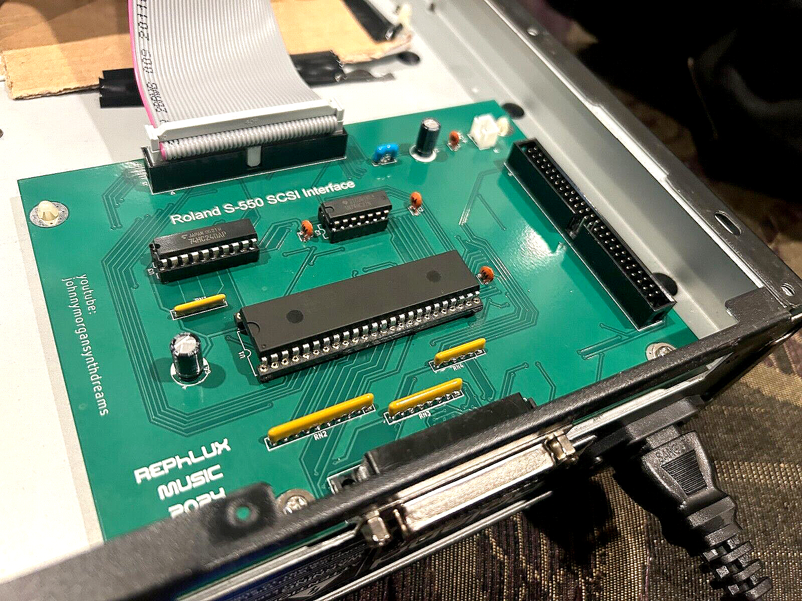
|
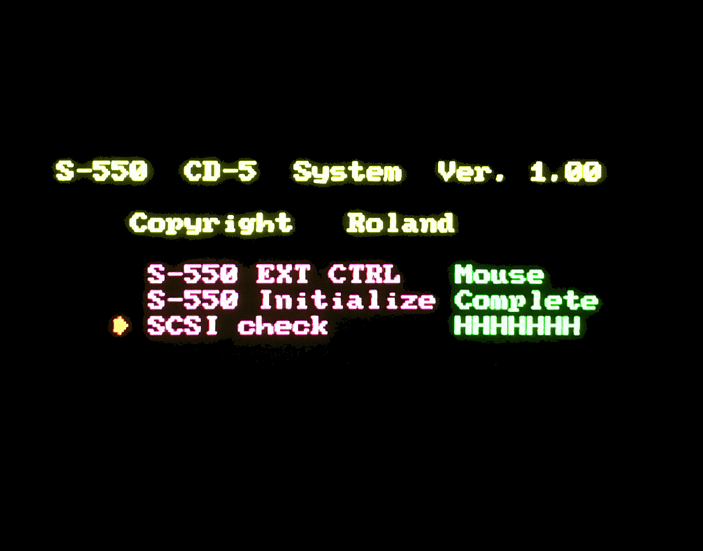
(click for larger image) |
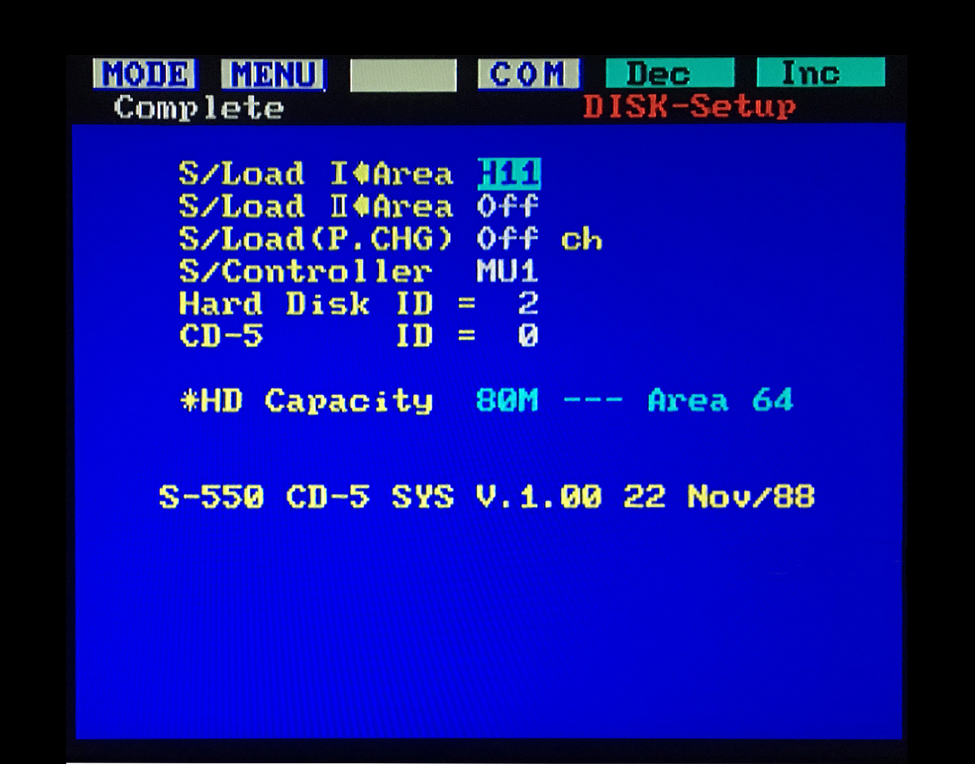
|
SCSI2SD Device With MicroSD Cards
SCSI2SD
Note: The SCSI2SD project is somewhat outdated these days due to lack of hardware availability
SCSI2HD information previously available on this page has been moved to a separate page at this link
SCSI Hard Drives, CD-ROM's, ZIP Drives And Other SCSI Projects
Note: SCSI Hard Drive, Zip Drive, KW-30 and other SCSI projects previously available on this page have been moved to this link
W‑30 Jog Wheel And Encoder Replacement
Several quality options for replacing your jog wheels and/or encoders
W‑30 Jog Wheel & Encoder DIY
Real‑Time Filter Control For Your W‑30
A very cool, easy and inexpensive DIY using a minimal amount of parts. These same functions can be performed using the Roland EV‑5 or EV‑7 Expression Pedal
W‑30 Real‑Time Filter Control DIY Video
(This Links To A YouTube Video)
W‑30 Filter Control Sample Files (W-30_Techno_Sounds.zip)
The creator of this very cool DIY sent me some custom W‑30 samples which really take advantage of the different filter controls
| EV-5 / EV-7 EXPRESSION PEDAL
This foot pedal is a variable resistor for controlling different parameter functions on the W‑30. Depending on how the EV‑5 control jack is assigned, this pedal can modify Control Changes in real‑time. The W‑30 Control Change parameters which can be changed using an EV‑5 are
#1 = Modulation #2 = Breath Controller #7 = Volume #64 = Hold/Sustain
The video bleepbit posted above has info on his webpage which states, "...the trick is to set the EV‑5 to receive the Control 2 (Breath Controller) and the Breath Controller to the Aftertouch (to do it press Config 2 / F4 in the Performance Mode) and save your preferences to the System Disk (Save / F1): Now, you can manage the cut‑off in your sounds by the real‑time filter." The EV‑5 retails for the outrageous price of $119 USD and the EV‑7 retails for even more at $279 USD. It is a very simple circuit and it is quite easy to make an equivalent tabletop hand controlled input device using a couple of inexpensive potentiometers, a 1/4" stereo plug, an enclosure and some 2‑conductor shielded cable Instead of buying the 1/4" stereo plug and 2‑conductor shielded cable separately, I suggest that you buy an inexpensive, ready‑made cable on eBay and snip off one end. That way, you'll have a 1/4" plug already soldered onto a cable which will eliminate extra work on your part. I have found this to be the least expensive route. I was able to build one for under $11 ‑ and that includes the shipping charges! Granted, it's not a true foot controller but, it's still a useful real‑time input device for the W‑30 and other samplers/synths, as demonstrated in the video above by bleepbit The EV‑7 and EV‑10 expression pedals are identical to the EV‑5 except they are housed in a metal case, not plastic. The EV‑10 had an extremely brief production run before it was replaced by the EV‑5. Recently, the EV‑7 seems to have been removed from the inventory of most online retailers 
Notes:
❖ Also works great with other samplers/synths including the Roland Alpha Juno‑1/2, HS‑10, JX‑10 and the MST Expressor Eurorack module ❖There is an optional add‑on polarity switch mod which enables EV‑5 compatibility with non‑Roland gear. Details for adding this optional switch into the circuit are here ❖The image shown on the right is a dual EV‑5 hand controller. This variation on the original design uses one 1/4" stereo output jack and one 3.5mm stereo output jack (hidden from view). Using output jacks instead of hard‑wiring the output cables was preferred since I already had several existing ready‑made cables. The knobs on top are the Main Controllers (VR1) Adjusting the EV-5 Minimum Volume Knob |
EV-5 DIY Parts List (Hand Controller Version) Tayda P/N: A-1982 - 10KΩ Linear Pot Tayda P/N: A-1983 - 50KΩ Linear Pot Tayda P/N: A-5081 - 1/4' Stereo Plug Tayda P/N: A-5166 - 1590A Enclosure 2 Conductor Shielded Cable (Shield = Ground) taydaelectronics.com 
Variation: DIY Dual hand controller with optional out jacks |


S‑550 And W‑30 Firmware: EPROM's or OTP EPROM's?
OTP v2.00 EPROMS Soldered Onto The S‑550 Main Board
These OTP EPROM's are found on later production runs
These OTP EPROM's are found on later production runs
It is unknown what the final firmware versions are for these two samplers but I suspect they are v2.02 (S‑550) and v1.03 (W‑30)
S‑550
The S‑550 has a pair of EPROM's on the Main Board labeled IC#3 and IC#6 which contain the sampler firmware. Depending on the production year, these IC's are either EPROM's with Quartz windows or One‑Time Programmable EPROM's (OTP). The easiest way to tell is:
- If they are in sockets and can be removed easily, they are EPROM's with Quartz windows (the label on top covers the Quartz window)
- If they are soldered onto the Main Board and the silkscreen on top reads "Roland", they are OTP EPROM's
Quartz Window EPROMS (W‑30 & S‑550)
These S‑550 EPROM's are found on earlier production runs
These S‑550 EPROM's are found on earlier production runs
Note: Unlike the W‑30, the S‑550 does not use ODD or EVEN EPROM's. Both IC#3 and IC#6 contain identical firmware code so you only need to backup one of the EPROM's and burn two of the same EPROM's when duplicating. Binary files for creating your own S‑550 EPROM's may be downloaded for free at the Synth & Sampler Binaries Webpage
To check the current firmware version of your S‑550 EPROM's, a monitor needs to be connected to the RGB port of the sampler
- Power on the S‑550 while holding down the [ 1 ] button on the DATA ENTRY KEYPAD
- Continue to hold down the [ 1 ] button until "Please Insert System Disk" is displayed on the monitor
- Continue to hold down the [ 1 ] button and insert System Disk v1.13 in the floppy disk drive, USB/FDD or SCSI2SD device
- Continue to hold down the [ 1 ] button while the disk loads and starts to counts down from 70 to 0
- When the countdown reaches 67, you may release the [ 1 ] button
- Press the [ DEC / NO ] button when the countdown is complete and "Next Disk Please?" is displayed
- Press the following buttons in order: [ FUNC ] [ MENU ] [ ∇ ] [ EXECUTE ] [ MENU ] [ 1 ] [ DEC / NO ]
     Ver # disp
     MT25 ROM. Ver. 2.01  05 AUG/88   (This Line Displays The EPROM Firmware Version#)
     S‑550 SYS. Ver 1.13  26 OCT/88   (This Line Displays The Floppy Boot Disk O/S Version#)
This is a list of all the S-550 EPROM firmware versions I have found in the wild
     MT25 ROM. Ver. 2.00   11 SEP/87
     MT25 ROM. Ver. 2.01   05 AUG/88
     MT25 ROM. Ver. 2.02   01 FEB/88
Through extensive testing, I have been unable to find any differences between these three versions. My best guess is that some minor changes were made to improve timing on the SCSI chain
W‑30
Every W‑30 I have ever seen (early and late production models) have both EPROM's IC#19 (EVEN) and IC#20 (ODD) socketed so they are much easier to work with. Also, I've never seen any version other than v1.03. The only real need to make copies of these two EPROM's would be to have a backup available in the event the electrons deplete over time. For more info about electron depletion, see the EPROM Quick Start Guide
To check the current firmware version of the W‑30 ROM's, power on the sampler while holding down the [ F1 ] button
A message similar to the following will be displayed:
W‑30 ROM Ver 1.03 [01/21]Note: Binary files for creating your own W‑30 EPROM's may be downloaded for free at the Synth & Sampler Binaries Webpage
W‑30 Custom Wave ROM's
Special Thanks go out to Ishibashi Hisao and Bernd Brüning for all of their hard work on this very cool and FREE W‑30 upgrade. It replaces the two default Wave ROM's with new code on the factory Wave ROM IC's and contains 32 new Wave samples. Vintage Drums, Oberheim, Moog, Juno and several others are included. For more information, see this YouTube video
Installation Instructions:
 The benefits of this amazing upgrade are numerous. However, unsoldering these large 32‑pin IC's should only be attempted by those with advanced soldering skills. The double‑sided PCB on the W‑30 poses a major risk if something goes awry
- Ensure you are properly grounded, working on a static‑free workbench or table and wearing eye protection during any soldering tasks
- Carefully unsolder the two original Wave ROM's on the MAIN PCB at locations IC29 and IC30
- NOTE: DO NOT confuse these new Wave ROM's with the main O/S EPROM's at locations IC19 and IC20
- The new Wave ROM's are 32‑pin IC's... NOT 28‑pin IC's
- Install two new 32-pin DIP sockets
- Download the custom code for the two new Wave ROM's
- This *.ZIP file contains the new Wave ROM Binaries and Custom Boot Disk

- Burn the new Wave ROM's for IC29 and IC30. Recommended blank EPROM's to use are:
- AT27C040-90PU / OTP - 4MB (512K x 8)
- TMS27C040-12JL / Quartz Window - 4MB (512K x 8)
- AT27C040-90PU / OTP - 4MB (512K x 8)
- After burning the new Wave ROM's, plug them into the new 32‑pin DIP sockets
- Ensure the IC notches are aligned correctly in the DIP sockets before you turn on the W‑30 ! ! ! ! !
- You will also need a new custom W‑30 Boot Disk to use these new Wave ROM samples (included in the download link from above). After starting‑up your sampler with a custom boot disk, the W‑30 will work just like before but it will have a new set of amazing default Wave ROM samples to work with. Included in the download link above are variations of W‑30 boot disks. Depending on the setup you are using, these are the new boot disks to use:
     v1.10 (Only 3.5" FLOPPY or GOTEK)
     v1.07 (SCSI2SD / HARD DRIVE / CDROM / ZIP DRIVE)
     v1.06 (Only 3.5" FLOPPY or GOTEK - Fast Boot)
     v1.01 (Only 3.5" FLOPPY or GOTEK - Old School Version)
| Replacement Power Switch [ MKS‑100, S‑220, S‑550, S‑750*, S‑770* and SP‑700* ] | |
|
* * * SPECIAL NOTE * * *
117V AC Models S‑750, S‑770 and SP‑700: The USA/Canadian models use this Power Switch P/N: 1312924 (ALPS SDGA3P) 110V / 230V / 240V AC Models S‑750, S‑770 and SP‑700: The Europe / UK / Latin / Asia models use Power Switch P/N: 1312939 (ALPS SDL1P-D) |
|
| ALPS P/N: SDGA3P
Sony P/N: 554‑880‑12 Power Rating: 5A @ 250V AC Type: ON/OFF w/Four Solder Lugs |

|
| If your old S‑550 switch is experiencing problems, don't bother trying to repair it. Some of the parts inside are sealed in plastic and other parts are wired in place. Repairing it is a lost cause. This power switch works with the S‑550, S‑220, MKS‑100 and a wide selection of other Roland synths and samplers including the D‑110, D‑550, GM‑70, JV‑880, MKS‑20, MKS‑50, MKS‑70, MKS‑80, and U‑220. In the 1980's and 1990's, this power switch was also used with a variety of Sony/JVC/Panasonic TV's and component stereo devices. This power switch is quite robust and therefore more expensive than most. Replacements can sometimes be found on eBay for about $10 (USD). Do a keyword search for "ALPS SDGA3P" | |
| Replacement Power Switch [ W‑30 / S‑330 / S‑750* / S‑760 / S‑770* / SP‑700* ] | |
|
* * * SPECIAL NOTE * * *
110V / 230V / 240V AC Models S‑750, S‑770 and SP‑700: The Europe / UK / Latin / Asia models use this Power Switch P/N: 1312939 (ALPS SDL1P-D) 117V AC Models S‑750, S‑770 and SP‑700: The USA/Canadian models use Power Switch P/N: 1312924 (ALPS SDGA3P) |
|
| ALPS P/N: SDL1P‑D
Power Rating: 5A @ 250V AC Type: ON/OFF w/Four Solder Lugs |

|
| If your old switch is experiencing problems, the outer shell is removable and the inner workings can most likely be repaired by cleaning the contacts only if you have the skillset and patience of a watchmaker and you like puzzles. Use caution if you attempt to repair this switch! My experience with this one proved they explode like a hand grenade because they are spring loaded. Use eye protection and only open the outer case while holding it inside a Ziploc baggie to keep the parts inside from flying across the room! Replacement switches can be found on eBay for only $2.50 (USD). Do a keyword search for "ALPS SDL1P‑D" or visit the jk_parts storefront on eBay | |
Factory supplied info for repairing S‑50 hardware and software bugs
S‑50 Service Information Sheets
Main PCB Board Assemblies And Power Supplies
S‑550
There are four different models of the S‑550 sampler. Each one uses a different transformer (110V, 117V, 220V or 240V). The DIY's shown above were installed and tested on five different S‑550 samplers. Four of the models tested use the 117V transformer and the fifth uses a 240V transformer. 117V And 240V transformer systems use identical Power Supply Board Assembly PCB's. Main CPU Board Assembly silkscreen part numbers on the five models tested were
- PCB #1 P/N: 79380120 00 AIN-32H UL94V‑0
- Very Early Production Model
- S/N: 830xxx w/socketed EPROM IC's v1.00
- S/N: 830xxx w/socketed EPROM IC's v1.00
- Very Early Production Model
- PCB #2, #3, #4 & #5 P/N: 79380120 02 AIN‑32H UL94V‑0
- Mid & Late Production Models
- S/N's: 853xxx, 864xxx, 867xxx & 886xxx
- S/N's: 853xxx, 864xxx, 867xxx & 886xxx
- Mid & Late Production Models
- USB/FDE was the only DIY tested on the 240V transformer system
W‑30
There are two different models of the W‑30 sampler each using a different Power Supply Board (110V/117V & 220V/240V). The DIY's shown above were installed and tested on two W‑30 models using only the 110V/117V transformer model. The Main CPU Board Assembly silkscreen part numbers on both models tested was
110V / 117V TDK PSU
(click for larger image)
(click for larger image)
- PCB #1 & #2 P/N: 76212120 UL94V‑0 AIN‑32H
- Very Early & Mid Production Models
- S/N's: AB0xxxx & AB1xxxx w/socketed EPROM IC's v1.03
- Very Early & Mid Production Models
It's interesting to note that the 110V/117V samplers (W‑30, S‑330, S‑750, S‑760 and SP‑700) all use the identical Power Supply Board. If you find yourself in a pinch and can't find a replacement power supply, one option might be to buy a "broken" sampler on eBay (i.e. one with a broken floppy drive, broken LCD, etc...) which has the same model power supply inside... provided it powers on, of course :^)
100V / 117V Power Board ‑ Roland P/N: 22443588 / MSA817
220V / 240V Power Board ‑ Roland P/N: 22443589 / MSA818
The schematic for this power supply is absent from the W‑30, S‑330, S‑750, S‑760 and SP‑700 Service Notes. A stripped down schematic and component layout does appear in the S‑770 Service Notes. However, there are no component values listed... only the PCB silkscreen numbers. From my experiences, the most common failure with this PSU are defective electrolytic capactiors which leak fluid over the years. A list of the original electrolytic capacitor values and locations for a 110V / 117V PSU is here. If it's not an easy fix due to failing capacitors, this model is extremely difficult to repair because TDK took extra precautions to protect their design by encasing some of the circuitry inside a layer of blue polyresin. Thus, some of these components can't be replaced or even identified. Thanks soooooo much TDK
Mean Well RPT-60C PSU (S-760 Replacement)
W-30, S‑330, S‑750, S‑760 and SP‑700 PSU's
I've been replacing all of my S‑760 PSU's with a Mean Well RPT-60C. It's a medical grade PSU and is only $25. Ray Bellis has designed a quality 3D bracket which is a highly recommended add‑on because this new PSU uses a live heat sink. The 3D bracket adds an extra level of safety. I have not installed the 3D bracket on the W‑30, S‑330 or SP‑700 yet so I'm unsure of the dimensions. Please verify before attempting to install in those models. Installation instructions for the S‑760 can be found at this link
There is also an excellent eBay store called scsi-connector which sells drop‑in PSU solutions and other DIY components for the S‑Series and W‑Series samplers. Check them out here
Disclaimer
Listed above are the Main PCB Board Assembly model numbers used for testing these DIY's. It's highly unlikely, but there is always a possibility that some modifications and add‑on gadgets will not work with other Main PCB Board Assembly models. Modifications made to any factory stock equipment will always pose an element of risk. Sometimes mistakes are made which are irreversible. The author is not responsible for any damage or injury resulting from this DIY info. Use this DIY information at your own risk
Listed above are the Main PCB Board Assembly model numbers used for testing these DIY's. It's highly unlikely, but there is always a possibility that some modifications and add‑on gadgets will not work with other Main PCB Board Assembly models. Modifications made to any factory stock equipment will always pose an element of risk. Sometimes mistakes are made which are irreversible. The author is not responsible for any damage or injury resulting from this DIY info. Use this DIY information at your own risk
Spare Parts Cross Reference Chart
I've compiled a small cross reference chart which is useful for matching duplicate spare parts on Roland synths and samplers. I use this list to find spares on broken equipment bargains found at eBay auctions. I just bought an S‑220 for only $23 which has enough spare parts for 19 different Roland synths and samplers. Gotta love eBay!
Spare Parts Cross Reference Cart
Tips For DIY Freaks Who Like To Save $$$. I picked this selection of gadgets and vendors because of the extremely LOW cost. I use everything shown here almost every day and highly recommend each one
Favorite DIY Tools And DIY Vendors
Safety Precautions
Modifications made to any factory stock equipment will always pose an element of risk. Sometimes mistakes are made which are irreversible. Improper soldering and handling of electricity can cause serious injury and damage the synthesizer. Use caution when handling static sensitive devices and the PCB. Make sure you are properly grounded, working on a static‑free workbench or table and wearing eye protection during any soldering tasks. The author is not responsible for any damage or injury resulting from this DIY info. Use this DIY information at your own risk. And, I can't stress enough, the importance of wearing eye protection while soldering. That stuff flies everywhere sometimes!
Modifications made to any factory stock equipment will always pose an element of risk. Sometimes mistakes are made which are irreversible. Improper soldering and handling of electricity can cause serious injury and damage the synthesizer. Use caution when handling static sensitive devices and the PCB. Make sure you are properly grounded, working on a static‑free workbench or table and wearing eye protection during any soldering tasks. The author is not responsible for any damage or injury resulting from this DIY info. Use this DIY information at your own risk. And, I can't stress enough, the importance of wearing eye protection while soldering. That stuff flies everywhere sometimes!
Other Synthesizer And Sampler Homepages I Maintain
All images, text, JavaScript and HTML Code ©1995- by llamamusic.com
The Information On This Page Is Current As Of
WEBSITE DISCLAIMER
Last updated October 31, 2014
1) You may not copy, reproduce, republish, disassemble, decompile, reverse engineer, post, make available to the public, or otherwise use the content of this website (including all software applications, scripts, web-pages, design elements, and graphics) for commercial gain in any way
2) By using the llamamusic.com website and its services you agree to be bound by these terms, which shall take effect immediately on your first use of this website. You may not use llamamusic.com services if you do not accept the terms. If you do not agree to be bound by all of the following terms please do not access and use llamamusic.com. llamamusic.com reserves rights to block violators of these terms from using its services or restrict their access in any form at any time
3) You agree that lawful owners of llamamusic.com own all legal right, title, copyrights, design rights, and other intellectual property rights (registered and unregistered) in this website and all content (including all software applications) located on the site
4) llamamusic.com website content and services are provided "AS IS" and on an "AS AVAILABLE" basis. To the extent permitted by law, llamamusic.com excludes all representations and warranties (whether express or implied by law), including the implied warranties of satisfactory quality, fitness for a particular purpose, non-infringement, compatibility, security, and accuracy. llamamusic.com does not guarantee the accuracy, completeness, or performance of the website or any of the content and services. While we try to ensure that all functionality provided is correct, no responsibility is accepted by or on behalf of llamamusic.com for any errors or inaccurate content on the website
5) llamamusic.com shall not be liable for any of the following losses or damage (whether such damage or losses were foreseen, foreseeable, known, or otherwise): (a) loss of data; (b) loss of revenue or anticipated profits; (c) loss of business; (d) loss of opportunity; (e) loss of goodwill or injury to reputation; (f) losses suffered by third parties; or (g) any indirect, consequential, special or exemplary damages arising from the use of llamamusic.com and its services regardless of the form of action
6) You agree to use this website only for lawful purposes, and in a way that does not infringe the rights of, restrict or inhibit anyone else’s use of llamamusic.com
7) The information provided by llamamusic.com ("we," "us," or "our") on llamamusic.com (the "Site") is for general informational purposes only. All information on the Site is provided in good faith, however we make no representation or warranty of any kind, express or implied, regarding the accuracy, adequacy, validity, reliability, availability, or completeness of any information on the Site. UNDER NO CIRCUMSTANCE SHALL WE HAVE ANY LIABILITY TO YOU FOR ANY LOSS OR DAMAGE OF ANY KIND INCURRED AS A RESULT OF THE USE OF THE SITE OR RELIANCE ON ANY INFORMATION PROVIDED ON THE SITE. YOUR USE OF THE SITE AND YOUR RELIANCE ON ANY INFORMATION ON THE SITE IS SOLELY AT YOUR OWN RISK
EXTERNAL LINKS DISCLAIMER
The Site may contain (or you may be sent through the Site) links to other websites or content belonging to or originating from third parties or links to websites and features in banners or other advertising. Such external links are not investigated, monitored, or checked for accuracy, adequacy, validity, reliability, availability, or completeness by us. WE DO NOT WARRANT, ENDORSE, GUARANTEE, OR ASSUME RESPONSIBILITY FOR THE ACCURACY OR RELIABILITY OF ANY INFORMATION OFFERED BY THIRD-PARTY WEBSITES LINKED THROUGH THE SITE OR ANY WEBSITE OR FEATURE LINKED IN ANY BANNER OR OTHER ADVERTISING. WE WILL NOT BE A PARTY TO OR IN ANY WAY BE RESPONSIBLE FOR MONITORING ANY TRANSACTION BETWEEN YOU AND THIRD-PARTY PROVIDERS OF PRODUCTS OR SERVICES
AFFILIATES DISCLAIMER
The Site may contain links to affiliate websites. Our affiliates include the following:
• supersynthprojects.com • vecoven.com • super-jx.com
| If you find some of this DIY info useful, please consider donating a small amount. All donations are used for future DIY sampler development and free info. Thanks!
|
|


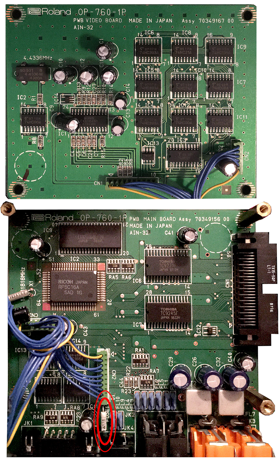