If you find some of this DIY info useful, please consider donating a small amount. All donations are used for future DIY sampler development and free info. Thanks!
I think these two topics are important enough to place at the top of all my synth INFO webpages 1) I buy a lot of broken synths on eBay and I'm able to fix about 90% of everything I find. It's usually a simple fix. If you have a synth with no power or intermittent problems after it warms up, it's probably due to the fact that back in the 1980's Roland and other synth makers used sub‑par solder and/or not enough solder to hold components in place. After 30+ years, the solder begins to break down and hairline fractures appear. This occurs at a higher rate for components which generate a lot of heat like Bridge Rectifiers, Power Transistors, large Electrolytic Capacitors, power input jacks and audio jacks which get a lot of use. The best approach is to use a magnifying glass and carefully inspect the backside of the circuit board. If you spot any suspect areas, re‑flow a hefty amount of NEW solder
2) I receive a lot of eMails and field many questions at synth related forums and also on Facebook. The most common question I get about problems with a synth has to do with errors when trying to load Patches and Tones. About 99.9% of the time, the problem always turns out to be a crappy MIDI interface. If you have a cheapo MIDI interface which looks similar to the one shown on the right... throw this piece of shit in the trash! Do It Now. Seriously! This thing is total junk and you get what you pay for. Inexpensive MIDI interfaces like this are unable to properly regulate the buffering of MIDI data. They will work fine with simple messages such as CC, Note On, Note Off, etc... however, when you try to send SysEx messages which are much longer, the SysEx data cuts off after only sending a few bytes. Investing in a higher quality MIDI interface will solve Load/Save errors and other communication problems. Also, if you experience errors when transferring Patch and Tone data from a computer to a synthesizer, DON'T use a USB hub. Plug your MIDI interface directly from the computer to the synthesizer. Why? Some external USB hubs fail when multiple USB devices are attached because there is not enough power to share. Small power sags will suddenly cause one or ALL of the attached USB devices connected to the hub to fail, often accompanied with a "disconnect" signal
These MIDI interfaces have been tested and will work with large SysEx Dumps:
       ✓ Focusrite Scarlett 2i4 2nd Gen   ✓ M-Audio Profire 2626        ✓ ESI Midimate eX         ✓ ESI Midimate II
       ✓ Focusrite Scarlett 4i4 2nd Gen   ✓ Miditech MIDIface II Thru   ✓ Yamaha UX 16 USB/MIDI   ✓ MOTU 823 mk3
       ✓ Focusrite Scarlett 6i6 3rd Gen   ✓ Tie Studio MIDI 1i1o        ✓ Miditech MIDIface 4x4   ✓ RME FireFace UC 2X2
       ✓ iConnectivity mio 1x1            ✓ iConnectivity mioXC 1x1
These MIDI interfaces are shit and do not work with large SysEx Dumps(some might w/special driver):
      ✗ AVID/M-Audio Fast Track Pro      ✗ M-Audio MIDISport UNO        ✗ M-Audio MIDISport 1x1  ✗ M-Audio Uno
      ✗ M-Audio MIDISport 2X2            ✗ Lekato MIDI USB              ✗ Hosa USM-422 MIDI      ✗ Fore MIDI Interface
      ✗ DigitalLife MIDI-C01             ✗ Hosongnic, HiFangeow, etc...
U-20 RS-PCM=U-20 RESYNTHESIZED -PULSE CODE MODULATION
"The U-110 (or, rather, its unreleased prototype, the T-110) is the ancestor of almost all Roland's synths and workstations from 1991 onwards. This makes it one of the most significant synths ever released. The problem with the U‑110 was that its digital‑to‑analogue converters were rather noisy. This was cured in 1989 with the release of the U‑220, which sounded much more 'high‑end'... the U‑20... possibly the first affordable keyboard that you could take on stage to produce convincing piano, organ, strings, brass, drums... as well as many other pads, effects, leads, basses and other important sounds. Leaping from the back pages to the front of Roland's catalogues, the U‑20 was a winner." --- Sound On Sound, 2005 ---
The most common praises about this keyboard are the realistic piano sounds within. In fact, some people made their U‑20 purchase decision based on Patch I‑11 Acoust Piano. If you go searching the Internet for the U‑20, you will find that this is one of those keyboards that people either really, really like... or totally despise. The U‑20, U‑220 and U‑110 are infamous as having some of the absolute worst user interfaces... ever. It's up there with the D‑110. The chaotic and cryptic Owner's Manual and the Red Epoxy Syndrome sealed the deal and quickly placed the U‑20 in a Top 10 List - "Most Hated Keyboards Of All‑Time". Personally, I really, really like this keyboard. It may be old technology, but I have been using it as my main keyboard controller since 1990, took it on the road for several live gigs, and it has always performed well. One of the sounds which shows off the versatility of this keyboard is Patch I‑83 Velo Combi. Playing the keyboard very soft will produce a piano sound, playing with medium velocity makes an ethereal Vox sound and playing the keys hard creates a Super Strings sound. Love it!
A common user complaint is that the built‑in Arpeggiator does not send notes out via MIDI. This simply is not true. In fact, it is quite easy to setup the U‑20 to output Arpeggiator notes via MIDI (see page 92 of the Owner's Manual). Other complaints are faulty key sensors not triggering notes, slow response times, lackluster Aftertouch response and the dreaded Red Epoxy Syndrome. Issues with faulty key sensors appear after a couple decades of use. The fix is usually made by cleaning the contacts with distilled water and a Q‑Tip. Guy Wilkinson explains the cleaning process in detail at supersynthprojects.com. For the Red Epoxy Syndrome, one of my U‑20's is fine and the other two had a major meltdown... literally. I think it's a combination of where your U‑20 was on the assembly line queue and where your synth has been stored over the years. For issues with slow response times, see this section. The Aftertouch on both of my U‑20's is a definite problem. The Aftertouch on my Alpha Juno‑2, JX‑10 and S‑50 stopped being responsive over a period of time. It's a common problem and an easy fix for these three synths. After cleaning the Aftertouch strips on those synths, the problem was resolved immediately. I have seen documentation on the Internet about an Aftertouch mod for the U‑20 which involves changing some resistor values on the Bender Board but have not attempted this fix yet. From a repair standpoint on the U‑20, to me it looks like fixing the Aftertouch is a lost cause (see Aftertouch below)
* * * FAQ: U-20 * * *
QUESTION
ANSWER
Where Can I Find Owner's Manuals For The U‑20, U‑220, U‑110, D‑70, and Rhodes Model 660/760 Synths?
The U‑20, U‑220, and U‑110 Owner's Manuals are some of the worst synthesizer manuals ever written, IMO. The steps are unorganized and extremely difficult to follow. The complicated menu architecture of the U‑20 deserves a better guide but this is all that is available online
My webpages offer a little info about the D‑70 but not much. There is a good magazine article on the Utilities page and some basic info about the PCM ROM and RAM cards
All 64 factory preset Patches and a selection of Timbres SynthMania
Why Were The U‑20, U‑220 And U‑110 Rompler's So Popular In The 1990's?
U-20 Video Review by AudioPilzU-110 Video Review by AudioPilz
How Do I Fix A U‑20 Or U‑220 When Garbage Characters Are Displayed On The LCD Screen And The Keyboard Does Not Play Notes?
The Good News
If the characters showing on the LCD are a mix of symbols, letters and numbers, chances are good this is an easy fix. It's probably one of these three problems;
2) A corrupted SysEx file was loaded or a SysEx file was interrupted during the load process
Solution: Reload the Factory Preset Patches (or an alternate Patch bank)
3) The system was initialized, a circuit board was unplugged, inactivity while being stored in the attic, etc...
Solution: Reload the Factory Preset Patches (or an alternate Patch bank)
I'm always amazed at how Roland designed some behaviors of the U‑20, U‑220 and other synths. This was considered as "normal" operation... reset the synth, everything on the screen turns into garbage and the keyboard is useless. Not even a one line courtesy message like, "Load Patches". Yay! Go Roland
The Bad News
If the LCD display shows a bunch of thin vertical lines, the problem is more serious and will most likely require a LCD replacement screen or more extensive servicing by a Roland Authorized Service Center
Last Ditch Effort
After these synths are left unattended for long periods of time in storage, sometimes the O/S goes haywire and the settings become jumbled. If your LCD screen is blank (monkey vomit green) it's possible the Contrast Level has been automatically reset all the way down to zero. The LCD may be working just fine but you can't see anything. To adjust the LCD contrast blindly without being able to see any menu selections, follow these steps in order. Try it twice since you can't tell if you've made a mistake
U-20
Power on and wait 15 seconds
Press [ EDIT ]
Press the [ ◅ ] LEFT CURSOR five times then press [ ENTER ]
Press the [ ◅ ] LEFT CURSOR three times then press [ ENTER ]
Press the [ ▻ ] RIGHT CURSOR two times then press [ ENTER ]
Press the [ △ ] VALUE UP eight times then press [ ENTER ]
You should now see some text on the LCD
If you don't see anything on the screen then the LCD is probably toast
If you do see some text, Initialize The Synth Back To Factory Fresh Settings
U-220
Power on and wait 15 seconds
Press [ EDIT ]
Press the [ ◅ ] LEFT CURSOR three times then press [ ENTER ]
Press the [ ◅ ] LEFT CURSOR four times then press [ ENTER ]
Press the [ ▻ ] RIGHT CURSOR two times then press [ ENTER ]
Press the [ △ ] VALUE UP eight times then press [ ENTER ]
You should now see text on the LCD
If you don't see anything on the screen then the LCD is probably toast
If you do see some text, Initialize The Synth Back To Factory Fresh Settings
The LCD In My U‑220 Is Broken. How Do I Replace It?
U-220 With a $5 buydisplay.com LCD Installed
Top: Model ERM2402FS-1 (BLACK/WHITE)
Middle: Model ERM2402SBS-1 (WHITE/BLUE)
Bottom: ERM2402SBS-1 (WHITE/BLUE - Side View)
This low cost and easy solution gets your U‑220 up and running again. No soldering required. It's almost a "Drop‑In" solution. A slight modification to the steel frame inside is all it takes
Guy Wilkinson has done it again! An innovative repair for the U‑20 keyboard. It's a custom made flexible keyboard cable and PCB kit to get your synth up and running again. Amazingly, this kit does not require any soldering! The flexi‑cable is made of Polyimide, a high‑performance plastic used in the aerospace industry and has gold plated pads for the key contacts. There is also an extra section in the assembly guide with a very easy mod to improve the aftertouch, which has always been an issue with the U‑20... even when they were brand new. This new repair kit also works with the Roland D‑5 and another version works with the JD‑800. A new production run for this space‑age upgrade just started in January 2023 and all the info is available at supersynthprojects.com
It is also important to note that the factory installed keyboard on a U‑20 is particularly susceptible to dust particles and thin layers of deposits accumulating on the keyboard contacts which prevent the keys from making a good connection. It is recommended you keep the U‑20 under a dust cover when not being used and keep it in a non‑foam lined case or inside a carry bag when transporting it outside the studio. Guy Wilkinson and Jim Atwood both have excellent webpages which provide some tips for repairing various Roland keyboard problems including PCB repairs, dead key troubleshooting and cleaning key contacts. Every 10 years or so, some of the contacts on my U‑20 keyboard require cleaning to remove these deposits. Although this is a very tedious process to remove all of the keys and membrane pads, the actual "fixing" part only takes about 5 minutes by using a Q‑Tip and distilled water (or IPA... sparingly) to carefully clean the contacts on the keyboard flexible PCB and also on the small graphite dot on the rubber membrane above. I use the words carefully and sparingly because you don't want to rub the graphite off the membrane or the dot. These are both fragile components and there is an extremely thin layer of graphite on top which can be rubbed away if you are not careful. The hard part is disassembling and assembling all of the keys, springs and contact covers which takes several hours to complete
Also note that keyboard cases using certain types of Polyurethane and Polyethylene foam will actually cause the red epoxy goo underneath the U‑20 keys to break down and dissolve at an accelerated rate. This red epoxy goo will drip onto the PCB contacts and dissolve the graphite and PCB traces
How Do I Restore The U‑20 Factory Preset Patches Or Load An Alternate Set Of Patches?
To restore the Factory Preset Patches, you will need a Mac, PC or LINUX computer with a generic SysEx loader program such as SNOIZE (Mac) or SEND SX(Windows). It is also possible to quickly restore the Factory Preset Patches if you have an optional RAM Data Card. Info about restoring Factory Preset Patches from an optional RAM Data Card here
[ WARNING!!! Everything in the internal memory will be erased! ]
To perform a Bulk Load
1) Use the generic SysEx program on your computer to SEND the factory preset file U-20_Factory_Presets.SYX. The load process is automatic
2) The LCD display will show Receiving Exclusive. during the load process
3) If the Patches won't load or if you receive a MIDI Buffer Full! error message, try adjusting the speed of your SysEx program or check the MIDI interface you are using (See * Troubleshooting Bulk Load Errors)
If the Bulk Load procedure did not work, verify the following:
Connect MIDI Out and MIDI In cables between the U-20 and the computer
Is the U-20 set to the correct SysEx Channel and is SysEx turned on?
Press [ JUMP ] [ BANK 1 ]
Press [ ▻ ] RIGHT CURSOR
Use [ △ ] VALUE [ ▽ ] to set SysEx Device ID = 17
Press [ ▻ ] RIGHT CURSOR twice
Press [ △ ] VALUE UP to set Rx SysEx = ON
Press [ KEYBOARD ] + [ SOUND ] at the same time to resume normal play mode
Verifying this is only needed once (until the next time SysEx Device ID or Rx SysEx are changed)
Note: To change values faster, instead of using [ △ ] VALUE [ ▽ ] buttons, you can use the C2/VALUE
Slider Knob to increase/decrease
* Troubleshooting Bulk Load Errors
▻The MIDI Send and Receive settings on your computer might be too fast for a U‑Series synth MIDI buffer to handle. The U‑Series synths were designed back in Medieval times when the processor speed of a home computer was only 20MHz... much slower than the models of today at +5GHz. Try setting the MIDI transmit, Pause and Timeout speeds in your computer's SysEx program to smaller values. For my U‑20 and U‑220 setups, I use the following speeds with my SysEx file transfer program for the Mac called SNOIZE
Transmit Speed = 2,000 Bytes/sec
Pause Between Played Messages = 10ms
SysEx Receive Timeout = 380ms
▻ Do you have two MIDI cables connected? Two are required because SysEx uses both MIDI IN and MIDI OUT
▻ Is the MIDI interface connected to a USB hub? USB hubs are notorious for transfer glitches. Plug straight into the computer
▻ Another thing to check is the MIDI INTERFACE connected to your computer. Some inexpensive MIDI interfaces which look similar to this one are unable to properly regulate the buffering of MIDI data. Some of these inexpensive MIDI interfaces will work fine with simple messages such as CC, Note On, Note Off, etc... However, when you try to send SysEx messages which are much longer, the SysEx data cuts off after only sending a few bytes. Investing in a higher quality MIDI interface may solve Load/Save errors and other communication problems
How Do I Restore The U‑220 Factory Preset Patches Or Load An Alternate Set Of Patches?
The process for loading Patches into the U‑220 is automatic. When a request from a PC, a Mac or a hardware sequencer sends a set of 64 Patches to the U‑220, the U‑220 will acknowledge and start to receive the Patch data. The U‑220 LCD will show "Receiving SysEx." and the MIDI MESSAGE LED above the power switch will blink rapidly. To restore the Factory Preset Patches, you will need a Mac, PC or LINUX computer with a generic SysEx loader program such as SNOIZE (Mac) or SEND SX(Windows) and a SysEx file with the U‑220 Factory Presets
Before transferring a SysEx file, ensure you have the following set on your U‑220: Rx Control Ch=01
RxSysEx = ON
SysEx Device ID=17
To verify these settings are correct, power on the U‑220 and wait 15 seconds
Press [ EDIT ] Button
Press the [ ◅ ] LEFT or [ ▻ ] RIGHT CURSOR button and select Setup
Press [ ENTER ] button
Press the [ ◅ ] LEFT or [ ▻ ] RIGHT CURSOR button and select MIDI
Press [ ENTER ] button
Press the [ ◅ ] LEFT or [ ▻ ] RIGHT CURSOR button and select Rx Control Ch
Press the [ △ ] UP or [ ▽ ] DOWN VALUE button and change Rx Control Ch=01
Press the [ ◅ ] LEFT or [ ▻ ] RIGHT CURSOR button and select Rx SysEx
Press the [ △ ] UP or [ ▽ ] DOWN VALUE button and change Rx SysEx = ON
Press the [ ◅ ] LEFT or [ ▻ ] RIGHT CURSOR button and select SysEx Device ID
Press the [ △ ] UP or [ ▽ ] DOWN VALUE button and change SysEx Device ID=17
Press the [ EXIT ] button three times
Load the U-220 Factory Patch SysEx file into your SysEx file transfer program (i.e. Snoize, MIDI‑OX, etc...)
Use your SysEx program to transfer the SysEx file to the U‑220
The U‑220 LCD display will show "Receiving SysEx." and the MIDI MESSAGE LED will blink rapidly
Troubleshooting Transfer Errors ▻ One problem you might encounter is the 'MIDI Buffer Full!' error message. This, and other solutions, are shown in the section above called Troubleshooting Bulk Load Errors
How Do I Save All Of The Internal Patches And Timbres Of A U‑20 / U‑220?
To save all 64 Patches and 128 Timbres, you will need a Mac, PC or LINUX computer with a generic SysEx saver program
To Perform A Bulk Dump On The U‑20
Press [ DATA ] then use the [ ▻ ] RIGHT CURSOR to select Bulk and press [ ENTER ]
Press the [ ▻ ] RIGHT CURSOR to select Internal and press [ ENTER ]
At this point, initiate your computer's SysEx program to capture the incoming SysEx data stream
Use [ ▽ ] VALUE DOWN to select All and press [ ENTER ]
The LCD display will show"Transmitting Sysex."during the Bulk Dump process
When the Bulk Dump process has finished, the LCD display will briefly show"Function Complete."
Use your computer's SysEx program to save the Bulk Dump as a *.SYX file
Press [ KEYBOARD ] + [ SOUND ] at the same time to resume normal play mode
To Perform A Bulk Dump On The U‑220
Press [ DATA ] then use the [ ▻ ] RIGHT CURSOR to select Bulk and press [ ENTER ]
Press[ ▻ ] RIGHT CURSOR to select All and press [ ENTER ] and the screen displays
"Data/Bulk/All"
"Bulk Dump All"
At this point, initiate your computer's SysEx program to capture the incoming SysEx data stream
Press [ ENTER ] again and the LCD display will show "Transmitting Sysex." during the Bulk Dump process
When the Bulk Dump process has finished, the LCD display will briefly show "Function Completed."
Use your computer's SysEx program to save the Bulk Dump as a *.SYX file
Press [ EXIT ] three times to resume normal play mode
It's important to note that when Saving a U‑220 SysEx file, you will not see the green MIDI MESSAGE LED blink
The green MIDI MESSAGE LED is only active when the U‑220 receives SysEx messages
If the Bulk Dump procedure did not work, verify the following*
Connect MIDI Out and MIDI In cables between the U-20 and the computer
Is the U-20 set to the correct SysEx Channel and is SysEx turned on?
Press [ JUMP ] [ BANK 1 ]
Press the [ ▻ ] RIGHT CURSOR
Use [ △ ] VALUE [ ▽ ] to set SysEx Device ID = 17
Press the [ ▻ ] RIGHT CURSOR twice
Press [ △ ] VALUE UP to set Rx SysEx = ON
Press [ KEYBOARD ] + [ SOUND ] at the same time to resume normal play mode
* Note: Verifying SysEx is only needed once (until the next time SysEx Device ID or Rx SysEx are changed)
One problem you might encounter is the 'MIDI Buffer Full!' error message. Changing your transmission speed may solve this. The solution is shown two sections above. Look for Troubleshooting Bulk Load Errors
I Can't Get The U‑20 To Communicate With
My Computer When Using A Librarian, SysEx Program Or Sequencer. What Should I Check?
NOTE: Sometimes, the MIDI send and receive settings on a computer are too fast for the U‑20 MIDI buffer to handle. If you experience communication errors such as MIDI Buffer Full!, try setting the MIDI buffer size in your computer's SysEx program to a smaller value
Is the U-20 set to SysEx Device ID = 17?
Press [ JUMP ] [ BANK 1 ]
Press the [ ▻ ] RIGHT CURSOR
Use [ △ ] VALUE [ ▽ ] to set SysEx Device ID = 17
Is the U-20 set to Rx SysEx = ON?
Press [ JUMP ] [ BANK 1 ]
Press the [ ▻ ] RIGHT CURSOR twice
Press [ △ ] VALUE UP to set Rx SysEx = ON
Press [ KEYBOARD ] + [ SOUND ] at the same time to resume normal play mode
Is the computer Sound Card, MIDI Controller, SysEx Librarian, etc... set to MIDI Channel 1?
Is the computer Sound Card, MIDI Controller, SysEx Librarian, sending MIDI data to the U‑20?
Make sure the patch librarian or SysEx program can send and receive SysEx data to and from the U‑20
two MIDI cables connected? Two are required because SysEx uses both MIDI IN and MIDI OUT
>
ther thing to check is the MIDI INTERFACE connected to your computer. Some inexpensive MIDI interfaces which look similar to this one are unable to properly regulate the buffering of MIDI data. Some of these inexpensive MIDI interfaces will work fine with simple messages such as CC, Note On, Note Off, etc... However, when you try to send SysEx messages which are much longer, the SysEx data cuts off after only sending a few bytes. Investing in a higher quality MIDI interface may solve Load/Save errors and other communication problems
How Do I Change The Internal Back‑Up Battery?
You can test the voltage of the internal battery without opening the U-20. How cool is that?!?
See Internal RAM Test on this page
I recommend that you take your keyboard to a Roland Authorized Service Center because installing a new battery is a tedious task. Out of 12 synths, samplers and keyboards, replacing the battery on a U‑20 was the most difficult one I have encountered to date. But...... if you're a real sicko like me and insist on saving pennies because you have that foolish "I can do that myself" attitude...... then...... detailed instructions are available. A big advantage of taking it to a Roland Authorized Service Center is that if they accidentally "pop" an IC because of static discharge, the cost is on them;
How Do I Initialize The U‑20, U‑220 or U‑110 And Return It To A State Of "Factory Fresh"?
!!! WARNING !!!
This Will Render Your Synth Unplayable Until Patches Are Reloaded.
Everything In The Internal Memory Will Be Erased. Everything... As In EVERYTHING!
Back-up Your Patches Before Initializing Your Synth
U-20 Factory Reset (see WARNING!!!)
Press [ PART ] and [ RHYTHM ] simultaneously to enter ROM Play Mode
While holding [ MARK ] and [ JUMP ], press [ ENTER ] for Test Mode
While holding [ JUMP ], press [ NUMBER 7 ] and the screen displays "15. Memory Initialize"
Press [ ENTER ]
Press [ △ ] VALUE UP to confirm and the screen will show "Function Complete."
To exit Test Mode, while holding [ JUMP ], press [ EXIT ] and repeat ( [ JUMP ] + [ EXIT ] )
Press [ KEYBOARD ] + [ SOUND ] at the same time to resume normal play mode
Load The U-20 Factory Preset Patches via SysEx or RAM Data Card
U-220 Factory Reset (see WARNING!!!)
Press [ JUMP ] and [ VALUE Δ ] simultaneously to enter ROM Play Mode
While holding [ MARK ] and [ JUMP ], press [ ENTER ] for Test Mode
While holding [ MARK ], press [ PART INST ◅ ] and the screen displays "11. Memory Initialize"
Press [ ENTER ]
Press [ △ ] VALUE UP to confirm and the screen briefly displays "Function Complete."
To exit Test Mode, while holding [ JUMP ], press [ EXIT ] and repeat ( [ JUMP ] + [ EXIT ] )
Load The U-220 Factory Preset Patches via SysEx or RAM Data Card
U-110 Factory Reset (see WARNING!!!)
Turn the power on while holding the [ PART ] and [ EDIT ] buttons
64 Factory Preset Patches are automatically loaded by default via the on‑board ROM IC
I Plugged In An SN‑U110 PCM Card. How Do I Access The Tones On The PCM Card?
How Do I Adjust The Display Contrast Of The LCD Screen?
U-20
Press [ EDIT ]
Press the [ ◅ ] LEFT CURSOR several times to select SETUP (blinks) then press [ ENTER ]
Use the [ ◅ ] CURSOR [ ▻ ] to select LCD (blinks) then press [ ENTER ]
Use [ △ ] VALUE [ ▽ ] or the C2/VALUE Slider Knob to adjust the LCD Contrast (0 ‑ 15)*
Press [ KEYBOARD ] + [ SOUND ] at the same time to resume normal play mode
U-220
Press [ EDIT ]
Press the [ ◅ ] LEFT CURSOR to select SETUP (blinks) then press [ ENTER ]
Use the [ ◅ ] LEFT CURSOR [ ▻ ] to select LCD (blinks) then press [ ENTER ]
Use [ △ ] VALUE [ ▽ ] to adjust the LCD Contrast (0 - 15)*
Press [ EXIT ] three times to resume normal play mode
U-110
Press [ EDIT ]
Press the [ ◅ ] [ ▻ ] buttons to select UTIL (blinks) then press [ ENTER ]
Press the [ ◅ ] [ ▻ ] buttons to select LCD (blinks) then press [ ENTER ]
Adjust the contrast using the [ DEC ] [ INC ] buttons
Press [ EXIT ] three times to return to the Play Mode
* The contrast setting is saved the instant you change (just like all the other U-20 / U-220 settings)
The new setting is retained even if the U-20 / U-220 is powered off
Why Does My U‑20 Act Sluggish?
This could be caused by one or a combination of these four issues;
1) If the setting for SysEx Patch Dump is turned ON, this will cause the U-20 to spend unnecessary cycles sending SysEx data to the MIDI ports. Set this to SysEx Patch Dump = OFF* and you should notice improved response times when cycling through patches
Press [ JUMP ] [ BANK 1 ]
Press [ ◅ ] LEFT CURSOR two times
Press [ ▽ ] VALUE DOWN to set SysEx Patch Dump = OFF
Press [ KEYBOARD ] + [ SOUND ] at the same time to resume normal play mode
2) If more than three MIDI devices are plugged into the chain of MIDI THRU connectors, use an optional MIDI THRU box
3) Earlier versions of the U-20 ROM IC experienced delays which occurred when
Fast, dense chords are played
Large amounts of streaming MIDI data fill up the U-20's MIDI buffer
The setting Rx SysEx = ON
U-20's upgraded to the final ROM IC v3.03 will correct most delay issues
If upgrading to a newer ROM IC is not an option, try setting Rx SysEx = OFF*
Too many Program Change or Control Change messages could be overloading the MIDI buffer
Press [ JUMP ] [ BANK 1 ]
Press [ ◅ ] LEFT CURSOR three times
Press [ ▽ ] VALUE DOWN to set Rx SysEx = OFF
Press [ KEYBOARD ] + [ SOUND ] at the same time to resume normal play mode
* Remember to set SysEx Patch Dump = ON and Rx SysEx = ON when saving/loading Patch banks or using your synth and computer for sequencing
What is Active Sensing And How Do I Turn It OFF?
Active Sensing is a type of MIDI message which is used to implement a "safety feature". It can provide an automatic "MIDI Panic" control that will cause stuck notes and other undesirable effects to be resolved whenever the MIDI connection in‑between modules is broken or impeded in some way. Active Sensing will send a MIDI pulse over the wire every 300ms. Personally, I like to turn Active Sensing OFF because the MIDI Message LED's on the rest of my devices start going bat‑shit crazy like a strobe light. It's very distracting. I prefer to see MIDI Message LED's trigger only when I play something on the keyboard, send/receive SysEx data to/from a librarian or when a sequencer is in playback‑mode. It also unnecessarily fills up the MIDI buffer and makes troubleshooting more difficult. Sometimes, too many devices on a MIDI chain which have Active Sensing turned ON will cause MIDI buffer overflows and for a couple of seconds, MIDI notes will not reach the module being played
U-20
By default, the U-20 has Active Sensing turned ON. To turn it OFF
Press [ JUMP ] then [ BANK 2 ] then press [ ▻ ] RIGHT CURSOR five times to select Tx Active Sensing
Press [ ▽ ] VALUE DOWN and set it to Off
* This parameter can also be found within the EDIT menu: EDIT >> Setup >> MIDI >> Kybd >> TX Active Sensing
U-220
The U‑220 doesn't actually transmit Active Sensing messages like the U-20. However, the U‑220 is able to receive Active Sensing messages via its built‑in MIDI Monitor. To turn the MIDI Monitor on
Press [ DATA ] thenpress [ ▻ ] RIGHT CURSOR three times to select Util and press [ ENTER ]
Press [ ▻ ] RIGHT CURSOR one time to select MIDI Monitor and press [ ENTER ]
Press [ ▽ ] VALUE [ △ ] and set it to Run
(U-20 and U-220 MIDI Implementation Chart Excerpts)
How Do I Set MIDI Channels For Individual Parts On The U‑20 And U‑220?
U-20
Press [ EDIT ]
Use [ ◅ ] CURSOR [ ▻ ] to select Sound then press [ ENTER ]
Use [ ◅ ] CURSOR [ ▻ ] to select Part then press [ ENTER ]
Use [ ◅ ] PART [ ▻ ] to select the desired Part (1 through 6)
Use [ ◅ ] CURSOR [ ▻ ] to select Rx Ch.
Use [ ▽ ] VALUE [ △ ] to select the MIDI Receive Channel
U-220
Press [ EDIT ]
Use [ ◅ ] CURSOR [ ▻ ] to select Patch then press [ ENTER ]
Use [ ◅ ] CURSOR [ ▻ ] to select Prt. then press [ ENTER ]
Use [ ◅ ] CURSOR [ ▻ ] to select MIDI then press [ ENTER ]
Use [ ◅ ] CURSOR [ ▻ ] to select Rx Ch. then press [ PART/INST ] and select the desired Part (1 through 6)
Use [ ▽ ] VALUE [ △ ] to select the MIDI Receive Channel
So... What's The Purpose Of The Micro Slide Switch Labeled FIXED/VARIABLE On The Back Of The U‑220?
Important things to note about the FIXED/VARIABLE switch are:
If the MIX OUT jacks are being used, setting this switch to FIXED will set the volume output at maximum level regardless of the position of the front panel Volume knob. Setting this switch to VARIABLE will allow you to regulate the volume using the VOLUME knob
Theswitch has no effect on the headphone volume. When using headphones, you can always adjust the volume using the VOLUME knob
Theswitch has no effect on the sound that is being output from DIRECT OUT and you will not be able to regulate the volume using the VOLUME knob
Always turn the power off before changing the setting of this switch
How To Test The U‑20 To Make Sure Everything Is Working
[ Warning: Some Test Modes are *DESTRUCTIVE*. Backup All Internal Patches, Tones & RAM Card Patches!!! ]
To enter Test Mode
Press [ PART ] + [ RHYTHM ] simultaneously to enter ROM Play Mode
While holding [ MARK ] and [ JUMP ], press [ ENTER ] for Test Mode
* To exit Test Mode, while holding [ MARK ] and [ JUMP ], press [ EXIT ]
Test #1 [ JUMP ] + [ BANK 1 ] LCD Contrast Test (Adjust level by using the Pitch Bender)Test #2 [ JUMP ] + [ BANK 2 ] LED Test (Adjust speed by using the Pitch Bender)Test #3 [ JUMP ] + [ BANK 3 ] Internal RAM Test (Also shows the internal battery voltage. Cool!)Test #4 [ JUMP ] + [ BANK 4 ] RAM Card Test (Also shows the RAM Card battery voltage. Cool x 2!)Test #5 [ JUMP ] + [ BANK 5 ] PCM Card Test (See Notes Below)Test #6 [ JUMP ] + [ BANK 6 ] Internal PCM ROM Test (Outputs letters A - F if OK)Test #7 [ JUMP ] + [ BANK 7 ] Key + Button + Pedal + PCM Card Insert Tests (DP-2 Pedal)Test #8 [ JUMP ] + [ BANK 8 ] A/D Converter Test + Visual Aftertouch Tests (See Notes Below)Test #9 [ JUMP ] + [ NUMBER 1 ] Control Sliders + External Input Tests (C1, C2, EV-5 Pedal)Test #10 [ JUMP ] + [ NUMBER 2 ] MIDI I/O test. Connect MIDI IN to MIDI OUT w/cable. Press [ ENTER ]Test #11 [ JUMP ] + [ NUMBER 3 ] Sound Test #1 (Requires Connecting An Oscilloscope - See Service Notes)Test #12 [ JUMP ] + [ NUMBER 4 ] Sound Test #2 (Requires connecting an oscilloscope - See Service Notes)Test #13 [ JUMP ] + [ NUMBER 5 ] DAC MSB Adjustment (Requires connecting an oscilloscope - See Service Notes)Test #14 [ JUMP ] + [ NUMBER 6 ] Effect Test. Press and hold any key for more than 0.5 seconds
Test #15 [ JUMP ] + [ NUMBER 7 ] Memory Initialization (* * DESTRUCTIVE! * *)Test #16 [ JUMP ] + [ NUMBER 8 ] Factory Data Load from an M-256E or M-512E RAM Card (* * DESTRUCTIVE! * *)Notes:
a) [ JUMP ] + [ BANK ] -or- [ JUMP ] + [ NUMBER # ] indicates pressing both buttons simultaneously
b) "PCM Card Test" will only work with PCM Cards SN-U110-11 (in Slot #1) and SN-U110-01 (in Slot #2)
c) "A/D Converter Test" displays Pitch Bender and Modulation levels when using the Pitch Bender
d) See page 10 of the U-20 Service Notes for a detailed descriptions of all Test Modes
e) "Visual Aftertouch Test" shows how lame your U-20's Aftertouch can really be. I was only able to get
mine up to the 20 - 25 range... nowhere near 127... and I was really pressing hard. There is an easy and
inexpensive modification at the SuperSynth U‑20 DIY Page allowing a more responsive Aftertouch
How To Test The U‑220 To Make Sure Everything Is Working
[ Warning: Some Test Modes are *DESTRUCTIVE*. Backup All Internal Patches, Tones & RAM Card Patches!!! ]
To enter Test Mode
Press [ JUMP ] + [ VALUE△ ] simultaneously to enter ROM Play Mode
While holding [ MARK ] and [ JUMP ], press [ ENTER ] for Test Mode
* To exit Test Mode, while holding [ MARK ] and [ JUMP ], press [ EXIT ]
Test #1 [ JUMP ] + [ EDIT ] LCD Contrast & LED Test (△ VALUE ▽ = Contrast Control)Test #2 [ JUMP ] + [ DATA ] SRAM Test (Also shows the internal battery voltage. Cool!)Test #3 [ JUMP ] + [ EXIT ] PCM Card Test (See Notes Below)Test #4 [ JUMP ] + [ ENTER ] Internal PCM ROM Test (Outputs letters A - F if OK)Test #5 [ JUMP ] + [ ◅ PART ] Switch Test (Press panel switches in any order)Test #6 [ JUMP ] + [ PART ▻ ] MIDI I/O test. Connect MIDI IN to MIDI OUT w/cable. Press [ ENTER ]Test #7 [ MARK ] + [ EDIT ] DAC MSB Adjustment (Requires connecting an oscilloscope - See Service Notes)Test #8 [ MARK ] + [ DATA ] Sound Test #1 (Requires Connecting An Oscilloscope - See Service Notes)Test #9 [ MARK ] + [ EXIT ] Sound Test #2 (Requires connecting an oscilloscope - See Service Notes)Test #10 [ MARK ] + [ ENTER ] Effect Test (Connect To Amp. Press and hold VALUE △ for more than 0.5 seconds)Test #11 [ MARK ] + [ ◅ PART ] Memory Initialization (Press VALUE △ * * DESTRUCTIVE! * *)Test #12 [ MARK ] + [ PART ▻ ] Factory Data Load(* * DESTRUCTIVE! * *)Notes:
a) [ JUMP ] + [ *BUTTON* ] -or- [ MARK ] + [ *BUTTON* ] indicates pressing both buttons simultaneously
b) "PCM Card Test" will only work with PCM Cards SN-U110-01 (in Upper Slot) or SN-U110-01 (Lower Slot)
c) See Page 9 of the U-220 Service Notes for detailed descriptions of all Test Modes
How To Test The U‑110 To Make Sure Everything Is Working
[ Warning: This Test Mode Is *DESTRUCTIVE* And It Will Erase All Patches And Tones Stored In Memory!!! ]
[ Backup All Internal Patches And Tones Before Entering Test Mode!!! ]
To enter Test Mode
Press and hold [ DEC ] + [ INC ] buttons when powering on the U-110 The current firmware version will be displayed as Ver. x.xx
Test  #1  S-RAM CHECK
Test  #2  LCD CHECK
Test  #3  KEY & LED CHECK
Test  #4  BATTERY CHECK
Test  #5  MIDI CHECK
Test  #6  WAVE ROM CHECK
Test  #7  ROM CARD CHECK
Test  #8  DAC OFFSET ADJUSTMENT
Test  #9  DAC MSB CHECK
Test #10  SOUND CHECK
Test #11  OUTPUT CHECK

   To proceed to the next test, press the [ DEC ] + [ INC ] buttons simultaneously
   To return to the previous test, press both [ ◅ ] CURSOR [ ▻ ] buttons simultaneously

Note:
  See Page 8 of the U-110 Service Notes for detailed descriptions of all Test Modes
How Are U‑20 Settings Adjusted For The Arpeggiator?
Arpeggiator parameters which can be adjusted are
Type: UP, DOWN, UP & DOWN or RANDOM Rate: 0 through 100
To set the Arpeggiator Type;
Press [ EDIT ] then [ JUMP ] then [ ARPEGGIO ]
Use [ ◅ ] CURSOR [ ▻ ] to select Type (blinks)
Use [ △ ] VALUE [ ▽ ] to select UP, DOWN, UP & DOWN or RANDOM
Press [ KEYBOARD ] + [ SOUND ] at the same time to resume normal play mode
To set the Arpeggiator Rate;
Press [ EDIT ] then [ JUMP ] then [ ARPEGGIO ]
Use [ ◅ ] CURSOR [ ▻ ] to select Rate (blinks)
Use [ △ ] VALUE [ ▽ ] to select 0 through 100
Press [ KEYBOARD ] + [ SOUND ] at the same time to resume normal play mode
What Kind Of DSP Effects Are Built‑In To The U‑20 And U‑220?
Two basic effects are available: Chorus and Reverb/Delay. The effects routings through MIX OUT are as follows;
Dry: Part is not affected by the sound patch effect setting
Rev: Part is only affected by the reverb
Cho: Part is affected by chorus and reverb
Dir: Part is sent to the DIRECT OUT jacks
Additionally, when programming the Chorus section, it can be assigned before or after the Reverb section.
Chorus Effects Chorus 1: Standard chorus effect
Chorus 2: Richer and more pronounced effect
FB-Chorus: Chorus tending towards flanging
Flanger: As it says
Short Delay: A chorus with a noticeable delay
(Parameters available for LEVEL, DELAY TIME, MOD RATE, MOD DEPTH, FEEDBACK)
Reverb/Delay Effects Room 1: Standard room reverb
Room 2: Slightly bigger room reverb
Room 3: Warmer room reverb
Hall 1: Standard hall reverb
Hall 2: Warmer and bigger hall reverb
Gate: Weak gate reverb
Delay: Standard delay
Cross Delay: Standard left/right delay
(Parameters available for REVERB / DELAY TIME, LEVEL, DELAY FEEDBACK)
How Do I Troubleshoot And Repair The Aftertouch On A U‑20?
Non-responsive and lackluster Aftertouch seems to be a complaint from several U‑20 owners. I have three U‑20's. One is really lame when it tries to do Aftertouch and the other two initially did not have any Aftertouch at all
While running the Visual Aftertouch Test, I was only able to get mine up to the 20 - 25 range... nowhere near the maximum of 127... and I was really pressing hard... like the "I might break this key in half", kind of hard. I think the U‑20's Aftertouch problem can be remedied if the contact strips are cleaned. However, the Aftertouch membrane strips are glued in place and it looks like a delicate operation (see below). I've not attempted to remove this glue so the Aftertouch on my U‑20 #1 is still lame. My U‑20 #2 and #3 had no Aftertouch at all. That problem was twofold but I was able to fix it (kind of)
1) The ribbon connector was unplugged on my U‑20 #2, probably from the last owner monkeying around with the keyboard assembly
2) There was a broken solder joint on the Aftertouch ribbon cable connector board at CN2 on the Bender Board Daughter Board on my U‑20 #2 and U‑20 #3. This is also called the Jumper Board (U‑20 Service Manual P/N: 29‑2). It's a very tiny circuit board only 1cm wide (Figure 1)
After repairing these issues, the Aftertouch is working again but... it's just as lame as the Aftertouch on my U‑20 #1. This same Jumper Board problem also crops up on the Alpha Juno‑2 because it uses a nearly identical miniature circuit board to connect its Aftertouch ribbon cable
Aftertouch is initiated when a key is pressed down hard which forces two layered membranes together. Depending on how much contact is made between these two membranes will determine the Aftertouch level. I attempted to separate the two layers so I could get inside and wipe off any oxidation on the Aftertouch contacts (Figure 2). However, after about an inch into the removal, I soon realized they were attached together with an extremely strong glue. Why couldn't Roland have used their substandard Red Epoxy here instead? I decided to stop there for fear of ruining it and have given up on trying to repair the Aftertouch by cleaning the Aftertouch strip. However, there is one thing to try by way of electronics which will work...
Aftertouch Modification
There is a simple modification at the supersynthprojects.com website which can be performed without having to remove the keybed assembly. The modification adds a small multi‑turn potentiometer onto the Aftertouch circuit and is a "Set & Forget" fix. Highly recommended. Click here for detailed step by step instructions
(Figure 3 & Figure 4)
How Do I Repair A Keyboard Suffering From The Dreaded "Red Epoxy Syndrome"?
The Problem
The Red Epoxy Syndrome appears on several Roland keyboards manufactured in the late 1980's and early 1990's. A short list includes the JD‑800, JV‑80, JV‑1000, XP‑80 and U‑20*
The red epoxy is used to hold the keyboard weights in place on the underside of each key, white and black. It turns out the epoxy was defective. Over time, the epoxy breaks down by getting softer and the metal weights fall off. In extreme cases, the red glue seeps down into the case wreaking havoc and destroys traces on the PCB. The problem appears to occur more often in warmer climates. It has also been suggested not to store the synth in a foam padded case because it will speed up decomposition. The gas released by the case foam reacts with the red epoxy. After Roland noticed this defect, later production U‑20's were shipped with keys that had a black epoxy or a specially treated red epoxy as a fix
The Solution (literally)
Dissolve the red goop and then reattach the weights using a quality epoxy. Some people have reported good success at dissolving the red goop by using a sodium hydroxide solution (also known as NaOH, Lye or Caustic Soda). Others have reported success using Drain‑O drain cleaner. However, in a post over at gearsz.com from user XPARIS001, there is a method which costs less than the foul smelling, poisonous and flesh eating sodium hydroxide solution. It's a product called LA’s Totally Awesome All‑Purpose Cleaner (UPC#: 722429640222). It's non‑toxic and biodegradable. I used this on a full set of U‑20 white keys with good results. One of the best things is that there's no foul odor and this stuff is only $3 for a 1/2 gallon bottle. Not a mis‑print. $3 A Bottle! If you can't find the large bottle, they also sell smaller 16 oz. bottles (pour or spray) for only $1 (UPC#: 0722429320100). I found it at a Dollar Tree store right down the road from me. Bonus!
From my experience with removing the red goop, I suggest you follow these tips
When removing the keys from the keyboard bed, write down an ordered list of the numbers which are embossed on each key. The white and black keys all have numbers and/or letters on them. The numbers are located at the top rear (i.e. CF11, 1‑3, D11, 1‑1, EB12, CF12, etc...). You will need a list to know the correct sequence when reassembling. I have created an image which shows the correct sequence at this link
When removing the keys from the keyboard bed, keep the flat springs in order so you can place them back in the exact location as you found them. Take care not to bend them out of shape. These do not have numbers on them :^(
Page 3 of the Roland U‑20 Service Manual has a great step‑by‑step guide detailing the proper way to remove and replace keys
I found the best way to use this cleaner is to pour it over the keys into a pail and cover it with a large plastic bag then seal it with a large rubber band. Although the smell is minimal even without covering it, this step completely eliminates any chemical odor. Everyone in the house will thank you
An online visitor has discovered that leaving the pail of solution and keys in the sun all day will actually speed up the dissolve process. His weights were dropping out by mid‑afternoon
The red goop on my keys was not a drippy liquid but it was not a solid either. I'd say about halfway... like a slightly melted bar of chocolate. I left the keys in the solution for exactly 72 hours. Depending on how solid or liquidy your red goop is, 72 hours may be too long. After 48 hours, all of the goop was dissolved around the sides of the weights and the key could have been washed with water, dried and then have new epoxy applied. I waited longer for the weights to fall out. The weights never did drop out on their own as reported by others who have tried this. I still had to do extra work to remove each weight
I only submerged the white keys. The black keys used a different epoxy which was an off‑yellow color. It was very solid when poked with a needle and none had any red goop problems. 25 less keys to worry about. Yay!
When reattaching the weights, I recommend using Loctite Epoxy Instant Mix™ (UPC#: 079340686205). Only mix enough for 10 weights at a time or it will harden too quickly. You don't need to completely surround the weight with the epoxy as Roland did. They used a weaker epoxy (obviously!) and thus had to overspread it. Using a toothpick to apply two small "pencil eraser sized" dabs at the front and back will work fine (see image below). This is extremely strong stuff and perfect for gripping something like keys which see a lot of action. In the event you didn't notice when you removed the weights, the four dimples face inward and touch the key. My guess is these were designed to keep a small gap in‑between the weight and the key to increase the height of the epoxy layer for a stronger bond. Warning: Don't get any of this shit on your fingers or on top of the keys. Even when unmixed, the liquid components in the Loctite Epoxy are unforgiving. From experience, I always use latex gloves when using this stuff. No matter how hard you try to keep clean, you will always end up getting some on your fingers
Alternate Method Nixed
One comment I read online suggested arranging all the keys on a large cookie sheet with the weights facing up. Pour just enough solution in the channel of each key to cover the weight. The advantage of this is that you only need to use a small amount of solution. This method may be better suited for use with sodium hydroxide or Drain‑O because I tried it on one key as a test it and it did not work at all for me
When the red goop started to dissolve, it formed a jello. I kept adding more solution and the jello got thicker and thicker. After 48 hours I just gave up on it because the red goop was not dissolving
The playing surfaces of the keys are not cleaned at the same time as compared to submerging
Covering the entire cookie sheet to help cut down on the chemical odor is difficult
Two small dabs of Loctite Epoxy Instant Mix™
were used to reattach the key weights
Conclusion
If you have a low patience level, don't go anywhere near this project. It's a total nightmare. Over my five day ordeal, I used every curse word I know and invented two new ones. On the third day I muttered something out loud like, "...where's the nearest Roland Authorized Service Center?" and also checked eBay for any new U‑20 auctions. If you decide to do this refurb, the method I would choose is LA’s Totally Awesome All‑Purpose Cleaner as opposed to the sodium hydroxide method. I was a little disappointed that the weights did not fall off on their own. It caused some extra work but my goal was accomplished. I think that if your red goop problem is in a liquidy state, the weights will drop off just fine. I think the glue on my keys was harder than most. If you can't find LA’s Totally Awesome All‑Purpose Cleaner where you live, another product with the same ingredients is called Orange Plus All Purpose Cleaner. Both of these products are Orange Oil based. You may be able to find a similar product in your area by matching the ingredients which are: Orange Oil Blend, Ethoxylated Alcohol, Disodium Salt, Tetra Sodium EDTA and Hydroxy Sodium. The Material Safety Data Sheet for the one I recommended is here
* Keyboards with the red goop problem are EP‑9, JD‑800, JV‑50, JV‑80, JV‑90, JV‑1000, U‑20, XP‑80, XP‑90, D‑70 and VK‑1000. I'll bet the Roland Customer Service Department shit a brick when these keyboards started failing at the same time all over the world :^O
Extra Info
If you lost one or more of the steel keyboard weights, here are some specs so you can make your own
(I had a few weights missing on my U‑20 so I used three U.S.A. pennies filed down on the sides which acted as a good substitute)
How Do I Fix Unresponsive Or Broken Switches On The U‑20 Front Panel?
Use a small sharp pair of diagonal flush wire cutters and cut all four leads off from the top side of the PCB. Take extra care not to wedge the wire cutters in‑between the base of the tact switch and the PCB when cutting the leads. This places excess force on the eyelet trace on the underside of the PCB causing possible damage. Use a solder sucker, a fine tipped soldering iron or a stainless steel hollow desoldering needle and remove the leftover pins from the PCB holes. Remove any excess solder remaining in the holes. The eyelet traces on the brittle 30‑year old PCB are very fragile. Take extra care not to lift them off the surface of the PCB while desoldering. Using too much heat or keeping the soldering iron too long in one spot usually leads to this type of problem so use a low soldering iron temperature around 330 (C°)
The total number of tact switches needed for the U‑20 is 38. Do yourself a favor and buy a couple of spares because... shit happens
There are two types of tact switches to choose from. The original tact switches installed by Roland had a light touch Operating Force of only 1 Newton'. I prefer a harder press of 1.5 Newton
1)Brand Name: OMRON
Manufacturer P/N: B3F-6022
Mouser P/N: 653-B3F-60223 Operating Force:*1.5 Newton
Operating Life: 300,000 cycles
Size: 5mm (H) x 6mm (W) x 6mm (D)
2)Brand Name: OMRON
Manufacturer P/N: B3F-6020
Mouser P/N: 653-B3F-60203 Operating Force: 1.0 Newton
Operating Life: 1,000,000 cycles
Size: 5mm (H) x 6mm (W) x 6mm (D)
Note: These switches will also work for the Roland JV‑80, JV‑90, JV‑880, JV‑1080, JV‑2080 and XP-50
The original switches I previously recommended were manufactured by Panasonic but these have been discontinued
You may still be able to find some of these from other electronic supply houses online
Manufacturer P/N: EVQ-22705R (This part was marked as obsolete at mouser.com in August 2019) Manufacturer P/N: EVQ-21405R (This part was marked as obsolete at mouser.com in August 2019)
How Do I Fix Unresponsive Or Broken Switches On The U‑220 Front Panel?
U‑220 Tact Switch Replacement
Use a small sharp pair of diagonal flush wire cutters and cut all four leads off from the top side of the PCB. Take extra care not to wedge the wire cutters in‑between the base of the tact switch and the PCB when cutting the leads. This places excess force on the eyelet trace on the underside of the PCB causing possible damage. Use a solder sucker, a fine tipped soldering iron or a stainless steel hollow desoldering needle and remove the leftover pins from the PCB holes. Remove any excess solder remaining in the holes. The eyelet traces on the brittle 30‑year old PCB are very fragile. Take extra care not to lift them off the surface of the PCB while desoldering. Using too much heat or keeping the soldering iron too long in one spot usually leads to this type of problem so use a low soldering iron temperature around 330 (C°)
The total number of tact switches needed for the U‑220 is 12. Do yourself a favor and buy a couple of spares because... shit happens
There are three types of tact switches to choose from. The original tact switches installed by Roland had a light touch Operating Force of only 1 Newton*. I prefer a harder press of 2.6 Newton
An Error Message On my U‑20 LCD Says "Key Scanner Error". How Do I Fix That Problem?
No clue :^(
A visitor to this website had a U‑20 with this error. He took it to an Roland Authorized Service Center and they reported it was unrepairable
Who Is Crazy Enough To Remove A Version 2.00 Main Circuit Board From A Working U‑20 And Replace It With A Version 3.03 Circuit Board?
That would be me. The crazy one. I found a good deal on eBay for a Main Circuit Board with a Version 3.03 ROM IC soldered in. Since my spare U‑20 was running with an old Version 2.00 ROM (also soldered in), I wanted to see if I could swap them. Both boards were identical with the exception of ROM IC#8 and both boards had the same part numbers (U‑20 ASSY | 76213900 | 292‑735‑01). I had great results but there were a few minor roadblocks along the way. If you decide to do this upgrade, be aware of these issues
There are some ribbon cable hookups which use Wire Trap Connectors (Figure 1). I never worked with these before. I was unable to figure out how they worked until I posted a question online. Someone in the Synthesizer Spares or Repair Facebook group showed me how they work. After you know the secret, they are easy to remove. Your first inclination is to pry up the top of the connector and pull out the ribbon cable. Don't Do It. The cable ribbon is locked in place (Figure 2). You need to use your fingers or two small flat‑blade screwdrivers and push down on the side of the connector (Figure 3). This "unlocks" the ribbon wire from the connector making it easy to pull up and out
Remove the 3V battery before you swap the boards. Install the battery after all of the board cables are plugged in
There are plenty of ways to disable a U‑20. This could be one of them. This is a very risky and time consuming project. Especially risky are the wire trap connectors and cables. These cables are flimsy and after a few connects and disconnects, the wires start to bend and fray. They seem best suited for a one‑time use when they were first assembled at the factory. After a few weeks of use, I haven't noticed any compatibility issues between the v3.03 Main PCB and the other PCB's which were not changed out and previously connected to the v2.00 Main PCB (i.e. Switch Board Left, Switch Board Right, Bender Board, etc...). I'm not posting any instructions here because if you attempt this, you are obviously mechanically inclined enough to figure things out on your own. I'm posting this just to let others know it can be done if needed
Do you like to experiment with hardware setups?
If you have access to more than one U‑20 or U‑220, it's possible to transfer Bulk Dumps from U‑20 to U‑20, U‑220 to U‑220, U‑220 to U‑20 or U‑20 to U‑220. It's a simple process
In this example, A Bulk Dump is sent from a U‑220 to a U‑20
Connect U‑220 MIDI OUT to U‑20 MIDI IN
Connect U‑20 MIDI OUT to U‑220 MIDI IN
Initiate a "Bulk Dump All" on the U‑220
The U‑220 LCD will display "Transmitting Sysex."
The U‑20 LCD will display "Receiving Exclusive."
All Patches and Tones have been transferred from the U‑220 to the U‑20
Notes:
When sending a Bilk Dump from a U‑20, remember to select "Internal", not "Temp"
If you experience any issues, ensure that both synths are set to "SysEx Device ID = 17" and "Rx SysEx = ON"
Other Than A Keyboard, What Are Some Of The Main Differences Between The U‑20 And The U‑220 / U‑110 Sound Modules?
The U-220 and U-110 are unable to use M-256E or M-512E RAM Data Cards to store Patches and Tones
Several owners report that the U-110 is much noisier than the U-20 and U-220
The U-20 has two 1/4" input jacks for connecting an EV-5 Expression Pedal and a DP-10 / DP-2 Hold Pedal
The U-20 and U-220 have 2 PCM Expansion Card Slots. The U-110 has 4 PCM Expansion Card Slots
The U-110 has a different DSP effects structure than the U-20 and U-220
The U-110 and U-220 have more assignable outputs than the U-20
The U-110 has a lower sample playback rate than the U-20 and U-220
The U-110 has 2MB Internal ROM. The U-20 and U-220 have 3MB Internal ROM
Another minor difference between the U‑20 and U‑220 are the 64 factory Patches that Roland loaded onto the RAM chip before it left the factory. The timbres and waveforms hard‑coded inside the U‑20 and U‑220 on the ROM chips are identical so both will make the exact same sounds. There are eight Patches that are different between these two synths. However, it's a very easy fix. You simply take a U‑20 factory SysEx file and load it into a U‑220. SysEx files are interchangeable between these two models
U‑20 FACTORY PATCH SET
I‑11 through I‑38 (identical to U‑220)
I‑51 through I‑88 (identical to U‑220)
Q: Performance‑wise, how might this affect performing music on one or the other?
A: If you have U‑20 songs saved to sequencer files, during playback on a U-220, the sequencer might call up a SingingPiano (U‑220 Patch) instead of a FretlessBass (U‑20 Patch), for example.
What Are The Rules For Naming U‑20 / U‑220 / U‑110 Patches And Timbres?
The maximum character length for a U‑20 and U‑220 Patch/Timbre name = 12
The maximum character length for a U‑110 Patch/Timbre name = 10
The only legal characters in a U‑20 / U‑220 / U‑110 Patch or Timbre name are the following:
A through Z a through z 0 through 9 space - / + * . , : ; = ! " # $ % & ' ( ) < > { } [ ] _ ? ♪
(Note: The ♪ character is not available on the U‑110)
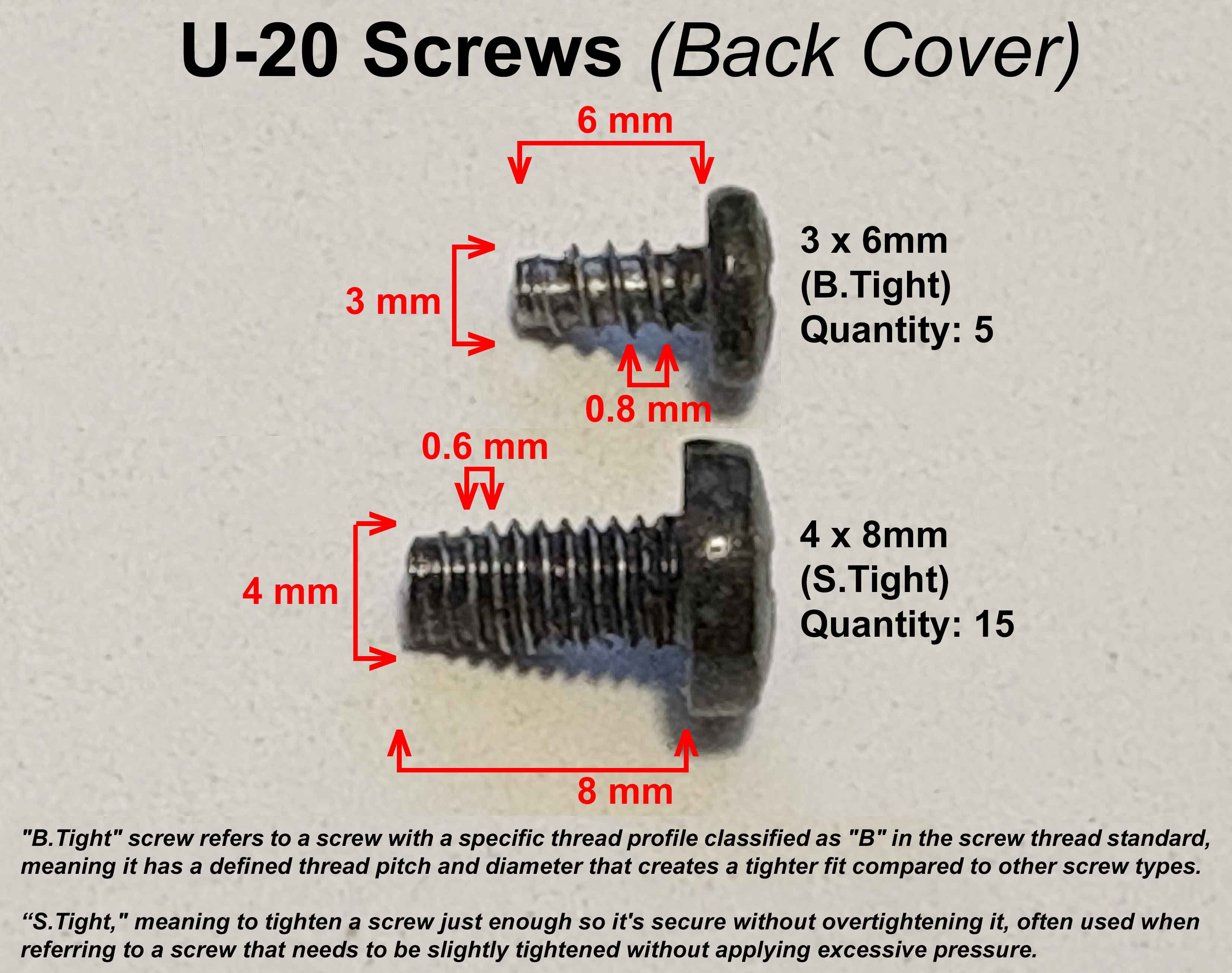
I Lost Some Screws For My U‑20. What Are The Sizes?
There is a list of some screw sizes at the Battery Replacement page
[ Warning: Checking the ROM IC version does a 'Soft Reset'. Backup your internal Patches!!!!! ]
U-20
In PLAY MODE section, press [ PART ] and [ RHYTHM ] simultaneously, to enter ROM PLAY
While holding [ MARK ] and [ JUMP ], press [ ENTER ]
* To exit, while holding [ MARK ] and [ JUMP ], press [ EXIT ]
U-220
Press [ DATA ] then use the [ ◅ ] [ ▻ ] buttons to select UTIL, press [ ENTER ]
Use the [ ◅ ] [ ▻ ] buttons to select ROM PLAY, press [ ENTER ]
While holding [ MARK ] and [ JUMP ], press [ ENTER ]
* To exit, while holding [ MARK ] and [ JUMP ], press [ EXIT ]
U-110
Turn the power on while holding the [ DEC ] and [ INC ] buttons
* To exit, press [ DEC ] + [ INC ] simultaneously to cycle through the remaining test screens
I was very surprised to find that both my U‑20 ROM and U‑110 ROM IC's were soldered directly onto the PCB and not socketed. Yipes!!! This change by Roland was made to cut production costs which was a horrible decision for techno geeks like myself who like to make backups of synth firmware and help other synth owners upgrade to the latest and greatest version. I've discovered that the ROM's installed on most U‑20's and U‑110's are not EPROM's but are instead MASK ROM's. It's nearly impossible to copy this MASK ROM binary code and burn it onto a regular EPROM unless you make your own custom rewired socketed adapter for your EPROM reader/burner
The Good News
If your U‑20 has a MASK ROM, the electron data will not deteriorate over time like that of a regular EPROM
The Bad News
If your U‑20 firmware is v1.x or v2.x, upgrading your firmware is nearly impossible. It would require unsoldering the old IC, figuring out a way to read a v3.x MASK ROM and burning it
Detailed info, old forum posts and ideas re: U‑20 MASK ROM upgrades can be found at this page
1) Problem with DSP Effects IC initialization corrected (almost). Spurious noise or no sound at all is noticed at times when you select Patch I-88 (v1.03 ROM)
2) Rhythm Part did not change level when MIDI Volume was received
3) Key Range settings were non-inclusive (v1.03 ROM)
4) Key Velocity ranges were set with Min and Max values (v1.03 ROM). This is changed to Offset (lowest value setting) and Sensitivity (how steeply the velocity will rise) with the v2.00 ROM
VER 3.01 ROM IC Fixes These Bugs
[unknown]
VER 3.03(a) ROM IC Fixes These Bugs
1) MIDI times are more responsive
2) Buffer overflow may occur when receiving MIDI SysEx
3) Problems with DSP Effects IC initialization. The Service Bulletin says, "...it seldom happens" ;^)
4) Parts 1 through 6 won't always recognize Poly Aftertouch
5) When a Tone is using two voices (as in "Velocity Mix" or "Detune") and it is assigned to "Rhythm Part", the level of the two voices will get unbalanced
6) When a voice in a Rhythm Part has stopped sounding, it is not released from the part
7) Volume Level 0 is not silent
❖ The following new parameters have been added
• Rx Volume, Rx Pan and Rx Hold can be set ON/OFF for each part
• Level Boost for Rhythm Part
The U‑20 power switch is the same part number used on several synths and other Roland gear including the Alpha Juno‑1/2, Super JX‑10, JX‑8P, Juno 60/106, JV‑80, JD‑800, D‑10/20/50/70, MK‑80, and MPU‑101
If your old switch is experiencing problems, don't bother trying to repair it. Some of the parts inside are sealed in plastic and other parts are wired in place. Repairing it is a lost cause. This power switch works with the U‑220 and a wide selection of other Roland synths and samplers including the D‑110, D‑550, GM‑70, JV‑880, MKS‑20, MKS‑50, MKS‑70, MKS‑80, MKS‑100, S‑220 and S‑550. In the 1980's and 1990's, this power switch was also used with a variety of Sony/JVC/Panasonic TV's and component stereo devices. This power switch is quite robust and more expensive than most. Replacements can be found on eBay for about $10 (USD). Do a keyword search for "ALPS SDGA3P"
* * * ACCESSORIES * * *
SN-U110 PCM Expansion Cards
Additional slots labeled "PCM CARD" on the U‑20/220/110, D‑70 and Rhodes Model 660/760 are for use with SN‑U110 PCM Expansion Cards. There are a total of 15 PCM Cards available from Roland which are used to expand the sound capabilities by adding hard-coded waveform samples into the synthesizer. It is important to note that two of those cards "SN‑U110‑08 Synthesizer" and "SN‑U110‑09 Guitar & Keyboards" are already hard‑coded on ROM IC's inside the U‑20, U‑220 and D‑70 so don't waste your money buying those unless it's for a U‑110. Also, be aware that "SN‑U110‑02 Latin Percussions" and "SN‑U110‑10 Rock Drums" are not compatible with the D‑70 (Note: Rhythm Kits contained on the SN‑U110‑02 Latin Percussions card don't work but the individual Tones do work). These PCM Expansion Cards are highly reliable because they are enclosed in a metal case, are shock & vibration resistant, have no moving parts inside and are able to withstand extreme temperatures from ‑40°C to 85°C (-40°F to 185°F)
I have listened to all of the Roland PCM Expansion Cards and the top three cards which impressed me the most are (in order)
1.SN‑U110‑12 - Sax & Trombone
(I'm totally bonkers about this card. Some of the most realistic saxophone samples I've ever heard)
2. (Tie) SN‑U110‑03 - Ethnic -and- SN‑U110‑02 - Latin And F.X. Percussions (An excellent selection of Sitars, Tablas, Balafons, Zings, Zaps, Boings, Vibraslaps and many more)
3.SN‑U110‑07 - Electric Guitar (Wayne's World! Wayne's World! Party Time! Excellent!)
A great reference site for SN‑U110 PCM Cards is available at BigRedRoo
To access the sounds of an SN-U110 PCM Sound Library Card plugged into a U-20
Press [ JUMP ] [ NUMBER 2 ] and the LCD Display shows
Edit/Timbre[1]/Tone
Tone = (x)-(yyy) (zzzzzzzzzz)x = PCM Card Number. For example, "SN-U110-11 Sound Effects" is PCM Card #11yyy = Tone Number on the PCM Card. For example, 004zzzzzzzzzz = Tone Name on the PCM Card. For example, WATERPHONE
Use the [ ▻ ] CURSOR to select x and it will start blinking
Press [ △ ] VALUE [ ▽ ] until one of the PCM Card Numbers (x) appears and starts blinking
Use the [ ▻ ] CURSOR to select the Tone Number on the PCM Card (yyy) and it will start blinking
Press [ △ ] VALUE [ ▽ ] to cycle through the available Tone Numbers (yyy) and Tone Names (zzzzzzzzzz) on the PCM card
Note: To speed up this process, instead of using [ △ ] VALUE [ ▽ ], you can use the C2/VALUE Slider Knob to cycle through the Tone names
For our example of using the SN-U110-11 Sound Effects PCM Card, the LCD display will read as;
Edit/Timbre[1]/Tone
Tone = 11-004 WATERPHONE11 = The PCM Card Number (SN-U110-11 Sound Effects)
004 = The Tone Number on the PCM Card
WATERPHONE = The name of the Tone on the PCM Card
If the LCD display looks something similar to what is shown below and says "No Card!", you will need to change (x) to match up with the PCM Card number(s)
       Edit/Timbre[1]/Tone
       Tone = (x)-(yyy)  No Card!
To access the sounds of an SN-U110 PCM Sound Library Card plugged into a U-220
Press [ EXIT ] three times
Press [ EDIT ]
Use the [ ▻ ] CURSOR to select Timbre and it will start blinking
Press [ ENTER ]
Use the [ ▻ ] CURSOR to select Tone and it will start blinking
Press [ ENTER ]
Edit/Timbre[1]/Tone
Tone = (x)-(yyy) (zzzzzzzzzz)x = PCM Card Number. For example, "SN-U110-11 Sound Effects" is PCM Card #11yyy = Tone Number on the PCM Card. For example, 004zzzzzzzzzz = Tone Name on the PCM Card. For example, WATERPHONE
The current Internal Tone will be displayed and the uppercase letter "I" will blink (x)
Press [ △ ] VALUE to select the PCM Card(x)matching the one inserted into the U‑220 (numbers will blink)
Use the [ ▻ ] CURSOR to select the Tone Number on the PCM Card (yyy) and it will start blinking
Press [ △ ] VALUE [ ▽ ] to cycle through the available Tone Numbers (yyy) and Tone Names (zzzzzzzzzz) on the PCM card
For our example of using the SN-U110-11 Sound Effects PCM Card, the LCD display will read as;
Edit/Timbre[1]/Tone
Tone = 11-004 WATERPHONE11 = The PCM Card Number (SN-U110-11 Sound Effects)
004 = The Tone Number on the PCM Card
WATERPHONE = The name of the Tone on the PCM Card
If the LCD display looks something similar to what is shown below and says "No Card!", you will need to change (x) to match up with the PCM Card number(s)
Some doofus on eBay is selling reproduction printouts of the SN‑U110 Sound Charts at $15 per card. Forget that shit! Roland Japan has them posted online in the Support section and you can download them for FREE. High‑resolution scans of all 15 SN‑U110 Sound Charts in one handy PDF file here
Bingo! You just saved $225
Roland Brand RAM Cards
The slot labeled "RAM CARD" on the back of the U‑20 is for use with Roland Memory Cards M‑256(D/E/G) and M‑512(D/E/G). These RAM Cards allow storage for an additional 64 Patches and 128 Tones. Both cards will work exactly the same. However, using an M‑512 RAM Card is overkill because the extra memory on the card is not accessed. The U‑20 was originally designed to work with the M‑256 RAM Card... before the larger M‑512 RAM Card was manufactured. RAM Memory Cards will not work with the U‑220 or U‑110. For unknown reasons, Roland decided to disable RAM Memory Card access for these two synths even though there was plenty of room to add a RAM Memory Card slot on the front panel
When inserting a RAM Card into the U‑20 for the first time ‑or‑ if the card contains data from a different model synthesizer, a message will appear on the LCD Display;
   It's a New RAM Card.
   Initialize it? [ENTER]
After initializing the RAM Card, "Function Complete." will appear on the LCD Display. All of the U‑20's internal Patches and Tones are automatically copied onto the RAM Card immediately after initialization
To access Patches on the RAM Card, press [ CARD/B ] [ BANK 1-8 ] [ NUMBER 1-8 ]
To save all internal Patches to the RAM Card
Press [ JUMP ] then press [ EXIT ]
Use [ ◅ ] CURSOR [ ▻ ] then [ △ ] VALUE [ ▽ ] to select "All"
Use [ ◅ ] CURSOR [ ▻ ] then [ △ ] VALUE [ ▽ ] to select "Int →Card" (ensure the arrow is pointing to the right)
Press [ ENTER ]
Press [ △ ] VALUE to confirm (responds with "Function Complete.")
Alternatively you could
Select "Int← Card" to load all the RAM Card Patches into the U‑20's internal memory
Select "Int←→Card" to exchange all the RAM Card Patches will all the Patches in the U‑20's internal memory
TROUBLESHOOTING
A visitor to the GR‑1 Homepage passed along some very useful info about troubleshooting a once working 256 RAM Card. Thanks for the info, Al! The problem was the error message "NOT GR1" would display but the system would not allow the card to be formatted. The solution was to perform a Full Copy (Dump) of the patches to the card. When the message "FORMAT?" is displayed, press "YES". The "COPY COMPLETED" message will appear. You can now read and write to the card. The standard "FORMAT" option only works for brand new un‑formated and un‑corrupted cards. If you are experiencing 256 RAM Card or 512 RAM Card problems on your U‑20, similar actions might be the solution
When inserting or removing cards from the "RAM CARD" slot, always make sure the switch on top of the card is set to the PROTECT position to prevent accidental erasure of any data. These cards use an internal lithium coin cell battery which the owner's manual says to replace every 2 years. However, I have found my battery lasting anywhere from 5 to 7 years. The replacement battery is P/N: CR2016
This amazing custom multi‑bank RAM card is a high quality item made in Germany. It's the equivalent of having 16 Roland M‑256 RAM cards on one device. It has switches on top so you can easily choose between the 16 individual banks. There's no battery and everything is stored on an MRAM chip. The cool thing is that this card works on my D‑110 and also works on other synths I own like the JV‑880, U‑20 and GR‑1. It has a lengthy compatibility list including the Roland A‑90, D‑5, D‑50, D‑550, D‑10, D‑70, JD‑800, JD‑990, JV‑1000, JV‑1080, JV‑2080, GR‑50, PM‑16, TR‑626, R‑880 (GC‑8), R‑8M, Akai MX‑1000, VX600 and others. It's possible to mix banks on one card so the ability to move this card between different model synths is convenient and a real money saver. For the DIY crowd, there are some interesting modifications discussed in the User Manual to emulate PCM ROM cards or increase the bank sizes anywhere from 16 x 256Kbit, 8 x 512Kbit, 4 x 1Mbit, 2 x 2Mbit or 1 x 4Mbit simply by adding some solder bridges
Update - January 2022: Sadly, Saga Musix no longer sells this RAM card but there is some Fantastic News! The designer of this multi‑bank RAM card has released the BOM and schematics into the DIY community for free. KiCAD PCB and Gerber files are available at github -or- you can order PCB's from OSH Park and build your own now for half the price of a brand new card. I have built six of these and they are all working great
Unfortunately, this will not work with the U‑220 or U‑110 because Roland did not add a RAM card slot to these modules when they designed it... only slots for PCM ROM cards
EV-5 / EV-7 EXPRESSION PEDAL
This foot pedal is a variable resistor for controlling different parameter functions. Depending on how the EXT CONTROL jack is assigned for individual Patches, this pedal can modify MIDI Control Changes in real‑time. The EV‑7 and EV‑10 expression pedals are identical to the EV‑5 except they are housed in a metal case, not plastic. The EV‑10 had an extremely brief production run before it was replaced by the EV‑5. Recently, the EV‑7 seems to have been removed from the inventory of most online retailers
One example of using an expression pedal to control a Patch is as follows;
Choose Patch I-46 Synth Bass 5
Press [ JUMP ] [ BANK 4 ]
Press [ ▻ ] CURSOR 5 times
Change the LCD Display to read "EXT:Ch Tx=Ch Ext #10"
Now whenever the expression pedal is moved up or down, the sound will pan left to right or right to left
The #10 setting is the Control Change parameter for Panning. Real‑time MIDI data is also sent
Other Control Change parameters can be set as well
#1 = Modulation#7 = Part Level#64 = Sustain
The EV-5 retails for the outrageous price of $119 USD and the EV-7 retails for even more at $279 USD. It is a very simple circuit and it is quite easy to make an equivalent tabletop hand controlled input device using a couple of inexpensive potentiometers, a 1/4" stereo plug, an enclosure and 2‑conductor shielded cable.
Instead of buying the 1/4" stereo plug and 2‑conductor shielded cable separately, I suggest that you buy an inexpensive, ready‑made cable on eBay and snip off one end. That way, you'll have a 1/4" plug already soldered onto a cable which will eliminate extra work on your part. I have found this to be the least expensive route. I was able to build one for under $11 - and that includes the shipping charges! Granted, it's not a true foot controller but, it's still a useful real‑time input device
Notes: ❖ Also works great with the Roland W‑30, Alpha Juno‑1/2, HS‑10, JX‑10, S‑50 and the Synthrotek MST Expressor Eurorack module ❖There is an optional add-on polarity switch mod which enables EV‑5 compatibility with non‑Roland gear. Details for adding this optional switch into the circuit arehere ❖The image shown on the right is a dual EV‑5 hand controller. This variation on the original design uses one 1/4" stereo output jack and one 3.5mm stereo output jack (hidden from view). Using output jacks instead of hard‑wiring the output cables was preferred since I already had several existing ready‑made cables. The knobs on top are the Main Controllers (VR1)
Variation: DIY Dual hand controller with optional output jacks
Adjusting the EV-5 Minimum Volume Knob
DP-6 PEDAL[ Momentary Switch For Hold Control / Patch Change ] DP-8 / DP-10 PEDAL[ Momentary Switch For Hold Control / Patch Change + On/Off Switch ]
The DP-6 and DP-8 have been discontinued but the DP‑10 will function in the same manner as the DP‑6 and DP‑8. Just set the Function Select switch to the "Switch" position (located on the side of the DP‑8 / DP‑10). The DP‑10 is equipped with a rubber plate on the bottom surface of the pedal. The DP‑8 does not have a rubber plate. This plate improves the stability of the pedal in use, making it less likely to slip even when used on a hard floor. To use, rotate the plate 90 degrees. The DP‑10 has a long 2.2 meter pedal cable. The DP‑8's cable length is 1.3 meters. Other than the points described above, the DP‑10 is identical to the DP‑8 in size and features. Both pedals are equipped with a Function Select Switch to adjust the pedal's functionality:
Half‑Damper Control:
Set the Select Switch to the Continuous Position to use the pedal to control half‑damper capability
Switch Control:
Set the select switch to the Switch position to use the pedal as an on/off switch
When you insert or remove a PCM card, this message will appear and operation will briefly halt. (This is normal)
It's a New RAM Card.
Initialize it? [ ENTER ]
The RAM card inserted into the RAM card slot has not been initialized for use by the U‑20
Action 1:
If the RAM card is new or if you want to use a RAM card from another device for the U‑20, press [ ENTER ]
The RAM card will be initialized, and internal memory data will be written into it. Use only M‑256 or M‑512 RAM cards
Action 2:
If you have mistakenly inserted the wrong card, remove it immediately
See the Troubleshooting Section if you are experiencing problems during format
PCM Memory Cards
Data/*****
RAM Card Protected
The protect switch of the RAM card is On, and writing is not possible. Turn the protect switch of the RAM card OFF, and try the operation again
Data/*****
Card Not Ready
Data/*****
RAM Card Verify Error!
When writing, saving or loading, the data was not correctly written into the RAM card. Make sure that the RAM card is correctly inserted, and try the operation again
RAM Card Battery Low!
The battery of the RAM card has run down. Replace the battery according to the instructions in the RAM card manual
Illegal PCM Card!
Please, take it out.
The card inserted into the PCM card slot is not a PCM card. Immediately remove the card from the PCM card slot
Receiving Exclusive.
Exclusive data is being received. Wait until reception ends (If the exclusive data being received is very short, this message will not appear)
Transmitting Exclusive.
Exclusive data is being transmitted. When transmission ends, the display will show "Function Complete", and then return to the previous display (If the exclusive data being transmitted is very short, this message will not appear)
SysEx Check Sum Error!
SysEx Data Length Error!
System exclusive data was incorrectly received. Check MIDI cables and the message that was transmitted, and try the operation again
Data/*****
Sure? [ VALUE Δ ] / [ EXIT ]
This message will always be displayed when you write data into internal memory or a RAM card. If you are sure you want to write the data into memory, press [ VALUE Δ ]
To quit without writing data into memory, press [ EXIT ]
Data/*****
Function Complete.
The write, save, or load operation has been completed. Wait for a short time until the previous display appears
MIDI Buffer Full !
If this error is shown while using a SysEx load/save program, the MIDI send and receive settings on the computer are too fast for the U‑20 MIDI buffer. Try setting the MIDI buffer size in your SysEx program to a smaller value
If this error is shown while communicating with another MIDI device such as an external keyboard or sequencer, too many Program Change or Control Change messages are being sent to the U‑20 and overloading the MIDI buffer
Try setting Rx SysEx = OFF
Press [ JUMP ] [ BANK 1 ]
Press [ ▻ ] CURSOR three times
Press [ ▽ ] VALUE to select Rx SysEx = OFF
Press [ KEYBOARD ] + [ SOUND ] at the same time to resume normal play mode
Another thing to check is the MIDI INTERFACE connected to your computer. Some inexpensive MIDI interfaces which look similar to this one are unable to properly regulate the buffering of MIDI data. Some of these inexpensive MIDI interfaces will work fine with simple messages such as CC, Note On, Note Off, etc... However, when you try to send SysEx messages which are much longer, the SysEx data cuts off after only sending a few bytes. Investing in a higher quality MIDI interface may solve Load/Save errors and other communication problems
Goofing Around With The LED's
I removed all of the boring red LED's and replaced them with Blue/Green/Red/Orange/UV/Yellow. Other than the hassles of opening the case and juggling four circuit boards around, this DIY is quite easy and it makes the U‑20 look much better and is more intuitive with color coded buttons. Feel free to use your own LED color scheme. Complete DIY instructions are here
All Of The Boring LED's Have Been Replaced
(click for larger image)
Favorite DIY Tools And DIY Vendors
Tips For DIY Freaks Who Like To Save $$$. I picked this selection of gadgets and vendors because of the extremely LOW cost. I use everything shown here almost every day and highly recommend each one
Other Synthesizer And Sampler Homepages I Maintain
If you find some of this DIY info useful, please consider donating a small amount. All donations are used for future DIY sampler development and free info. Thanks!
Safety Precautions
Modifications made to any factory stock equipment will always pose an element of risk. Sometimes mistakes are made which are irreversible. Improper soldering and handling of electricity can cause serious injury and damage the synthesizer. Use caution when handling static sensitive devices and the PCB. Make sure you are properly grounded, working on a static‑free workbench or table and wearing eye protection during any soldering tasks. The author is not responsible for any damage or injury resulting from this DIY info. Use this DIY information at your own risk. And, I can't stress enough, the importance of wearing eye protection while soldering. That stuff flies everywhere sometimes!
1) You may not copy, reproduce, republish, disassemble, decompile, reverse engineer, post, make available to the public, or otherwise use the content of this website (including all software applications, scripts, web-pages, design elements, and graphics) for commercial gain in any way
2) By using the llamamusic.com website and its services you agree to be bound by these terms, which shall take effect immediately on your first use of this website. You may not use llamamusic.com services if you do not accept the terms. If you do not agree to be bound by all of the following terms please do not access and use llamamusic.com. llamamusic.com reserves rights to block violators of these terms from using its services or restrict their access in any form at any time
3) You agree that lawful owners of llamamusic.com own all legal right, title, copyrights, design rights, and other intellectual property rights (registered and unregistered) in this website and all content (including all software applications) located on the site
4) llamamusic.com website content and services are provided "AS IS" and on an "AS AVAILABLE" basis. To the extent permitted by law, llamamusic.com excludes all representations and warranties (whether express or implied by law), including the implied warranties of satisfactory quality, fitness for a particular purpose, non-infringement, compatibility, security, and accuracy. llamamusic.com does not guarantee the accuracy, completeness, or performance of the website or any of the content and services. While we try to ensure that all functionality provided is correct, no responsibility is accepted by or on behalf of llamamusic.com for any errors or inaccurate content on the website
5) llamamusic.com shall not be liable for any of the following losses or damage (whether such damage or losses were foreseen, foreseeable, known, or otherwise): (a) loss of data; (b) loss of revenue or anticipated profits; (c) loss of business; (d) loss of opportunity; (e) loss of goodwill or injury to reputation; (f) losses suffered by third parties; or (g) any indirect, consequential, special or exemplary damages arising from the use of llamamusic.com and its services regardless of the form of action
6) You agree to use this website only for lawful purposes, and in a way that does not infringe the rights of, restrict or inhibit anyone else’s use of llamamusic.com
7) The information provided by llamamusic.com ("we," "us," or "our") on llamamusic.com (the "Site") is for general informational purposes only. All information on the Site is provided in good faith, however we make no representation or warranty of any kind, express or implied, regarding the accuracy, adequacy, validity, reliability, availability, or completeness of any information on the Site. UNDER NO CIRCUMSTANCE SHALL WE HAVE ANY LIABILITY TO YOU FOR ANY LOSS OR DAMAGE OF ANY KIND INCURRED AS A RESULT OF THE USE OF THE SITE OR RELIANCE ON ANY INFORMATION PROVIDED ON THE SITE. YOUR USE OF THE SITE AND YOUR RELIANCE ON ANY INFORMATION ON THE SITE IS SOLELY AT YOUR OWN RISK
EXTERNAL LINKS DISCLAIMER
The Site may contain (or you may be sent through the Site) links to other websites or content belonging to or originating from third parties or links to websites and features in banners or other advertising. Such external links are not investigated, monitored, or checked for accuracy, adequacy, validity, reliability, availability, or completeness by us. WE DO NOT WARRANT, ENDORSE, GUARANTEE, OR ASSUME RESPONSIBILITY FOR THE ACCURACY OR RELIABILITY OF ANY INFORMATION OFFERED BY THIRD-PARTY WEBSITES LINKED THROUGH THE SITE OR ANY WEBSITE OR FEATURE LINKED IN ANY BANNER OR OTHER ADVERTISING. WE WILL NOT BE A PARTY TO OR IN ANY WAY BE RESPONSIBLE FOR MONITORING ANY TRANSACTION BETWEEN YOU AND THIRD-PARTY PROVIDERS OF PRODUCTS OR SERVICES
AFFILIATES DISCLAIMER
The Site may contain links to affiliate websites. Our affiliates include the following:
• supersynthprojects.com • vecoven.com • super-jx.com


 FAQ - Manuals - Troubleshooting - Factory Presets - Aftertouch
 For additional info about the U-220 Sound Module, visit the BigRedRoo U-220 Page
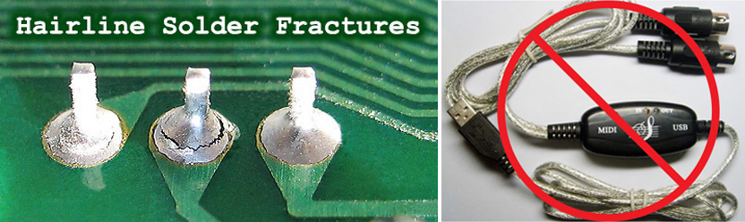


 Guy Wilkinson has done it again! An innovative repair for the U‑20 keyboard. It's a custom made flexible keyboard cable and PCB kit to get your synth up and running again. Amazingly, this kit does not require any soldering! The flexi‑cable is made of Polyimide, a high‑performance plastic used in the aerospace industry and has gold plated pads for the key contacts. There is also an extra section in the assembly guide with a very easy mod to improve the aftertouch, which has always been an issue with the U‑20... even when they were brand new. This new repair kit also works with the Roland D‑5 and another version works with the JD‑800. A new production run for this space‑age upgrade just started in January 2023 and all the info is available at